





Description
Key Technical Specifications
| Parameter | Value |
| Brand | ABB |
| Part Number | 7625013-S |
| Type Designation | Including PFSK 113 |
| Application System | ABB Stressometer Systems (6.0, 7.0, 7.1, 8.0, 8.1 FSA) |
| Component Group | Signal Transmission Unit (STU) / Measuring Roll |
| Contact Material | High-grade low-wear silver-graphite / carbon composition |
| Signal Level Compatibility | Millivolt (mV) and microampere (\muA) transducer signals |
| Customs Tariff Number | 85452000 |
| UNSPSC Code | 26101800 |
| Net Weight | 0.10 kg |
| Country of Origin | Sweden |
Product Introduction
The ABB 7625013-S, utilizing type designation PFSK 113, is a high-precision signal transmission brush block engineered strictly for ABB Stressometer flatness control systems. Installed directly within the Signal Transmission Unit (STU) housing on the shaft-end of a rotating measuring roll, this block maintains continuous, low-friction electrical contact with the slip rings. This allows millivolt-level force transducer signals to pass cleanly from the rotating roll to the stationary processing electronics without data corruption.
In cold rolling mills, any electrical noise or signal dropout directly impairs the system’s ability to calculate strip flatness accurately. The 7625013-S is manufactured with a specialized low-resistance carbon compound and high-tolerance spring-tension mechanics. This architecture eliminates electrical contact noise caused by mechanical vibration and oil mist, ensuring continuous, drift-free flatness telemetry during high-speed rolling operations.
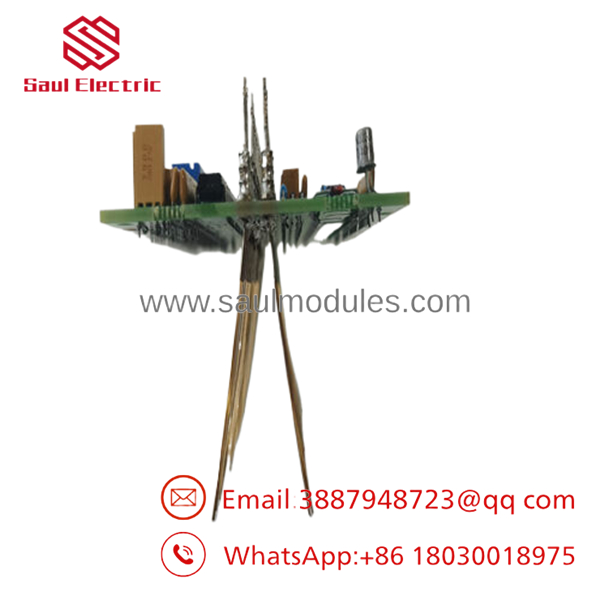
- 7625013-S
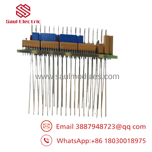
- 7625013-S
Installation & Configuration Guide
1.Pre-Installation Preparation & Safety:Estimated time: 10 mins.
Isolate the system and ensure a complete stop. Coordinate with the mill control room to ensure the specific rolling mill line is entirely locked out and the measuring roll has come to a complete mechanical halt. Turn off the auxiliary power supplying the local Stressometer electronics cabinet.
⚠️ Physical Safety Warning: Measuring roll positions are high-risk mechanical zones. Follow all mill site lockout/tagout (LOTO) protocols to prevent accidental roll rotation or strip tensioning while your hands are inside the STU housing.
Gather your tools: an ESD grounding strap, a metric hex key set, a precision torque screwdriver, lint-free technical wipes, specialty non-residue electrical solvent, and a smartphone for position logging.
2.Removing the Worn Brush Block:Estimated time: 10 mins.
Attach your grounded ESD wrist strap to the local machine frame. Remove the outer protective cover of the Signal Transmission Unit (STU) on the non-drive end of the measuring roll. Take a clear photograph of the internal brush block mounting orientation and wire routing paths.
Carefully back out the small electrical lead terminal screws. Do not drop the fasteners into the housing cavity. Release the mechanical spring-tension arm holding the brush block inside its guide holder. Slide the worn 7625013-S brush block straight out of its track slot. Inspect the guide tracks for carbon dust buildup or mechanical scoring.
3.Cleaning & Installing the New Block:Estimated time: 15 mins.
Before sliding in the new component, inspect the exposed rotating slip rings. Use a clean, lint-free cloth moistened with non-residue electrical solvent to wipe away all carbon tracks, grease residues, or fine metal dust from the ring surface.
Alignment and Tensioning (Critical): Slide the new 7625013-S brush block into the guide holder track. Verify it moves freely without binding. Gently lower the tensioning spring arm until it rests centered on the top of the carbon brush.
Reconnect the flexible copper shunt leads to the terminal block, torquing the terminal screws precisely to specification. Avoid twisting the shunt line, as it must move freely to allow the brush to feed forward naturally as it wears.
Self-Checklist:
- [ ] Slip ring surface is completely clean and bright with zero residue.
- [ ] The brush block slides smoothly vertically inside the guide track.
- [ ] Wires are routed clear of any spinning mechanical components or shafts.
4.Testing & Calibration Check:Estimated time: 15 mins.
Carefully reinstall the outer STU protective cover housing, ensuring all environmental seals are seated flush to block rolling oil mist. Re-energize the Stressometer controller rack.
Open the operator system diagnostics display page. Monitor the raw channel millivolt readings while the measuring roll is slowly turned or run at baseline idling speed. Confirm that the signal transmission registers low noise margins and shows zero random signal spikes or open-circuit data dropouts. Run the integrated software calibration routine to establish the new contact resistance baseline before clearing the mill line for live production.
Frequently Asked Questions (FAQ)
Q: Can I use a standard industrial motor brush as a cheap replacement for the 7625013-S?
A: Absolutely not. Standard motor brushes are engineered to carry high electrical current and voltage to drive a motor armature, and they often contain high carbon profiles that generate significant micro-arcing and noise. The 7625013-S (PFSK 113) is a specialized instrumentation component built with a high silver-graphite ratio. It is designed to transmit millivolt-level analog signals from piezoelectric sensors with nearly zero electrical impedance and noise. Using a standard motor brush will cause severe signal noise, corrupting the mill’s flatness measurement loops.
Q: How often should the 7625013-S brush blocks be inspected or replaced?
A: Replacement intervals depend heavily on your mill’s continuous running speeds, strip cleanliness, and internal STU sealing integrity. In standard high-throughput cold rolling applications, inspect the blocks every 3 to 6 months. Check for physical wear limits, uneven contact faces, or contamination from rolling oil. Replace the block immediately if the brush height has worn down past the manufacturer’s marked threshold line, or if you observe unstable baseline telemetry on the operator terminal.
Q: Will replacing this brush block affect my existing Stressometer calibration curves?
A: Changing the physical block does not alter the fundamental calibration coefficients stored inside the Stressometer processing system. However, a new brush block will have a slightly different contact resistance profile than the worn card it replaces. It is highly recommended to perform a standard system zero-taring or baseline diagnostic routine via the software utility once the new hardware is installed and spinning. This ensures optimal measurement accuracy from the first strip run.
Q: What causes premature wear or chipping on the contact face of this brush block?
A: Premature mechanical wear or edge chipping is almost always caused by mechanical runout on the slip rings, excessive spring tension, or an accumulation of hard metallic particles inside the housing track. If the slip ring surface becomes eccentric or scratched due to past bearing wear, it will act like a file against the silver-graphite brush face. Always check that the slip rings are smooth and round before sliding in a replacement block.
Q: Is the 7625013-S compatible across all versions of the ABB Stressometer system?
A: Yes, this component is designed for backward and forward compatibility across the primary Signal Transmission Units utilized in Stressometer 6.0, 7.0, and modern 8.0/8.1 FSA configurations. However, always verify your specific STU hardware assembly drawing number and serial number against the OEM datasheet prior to installation to ensure no custom mechanical modifications were applied to your specific mill configuration.

 Start Chat


