





Description
Key Technical Specifications
| Parameter | Specification Value |
| Number of Channels | 8 inputs (individually isolated channel-to-channel and channel-to-ground) |
| Input Signal Range | 4 to 20 mA, 0 to 20 mA, 0 to 5 V DC, 1 to 5 V DC |
| Analog-to-Digital Resolution | 16-bit successive approximation conversion |
| Module Input Impedance | 250 \Omega internal precision shunt resistor for current modes |
| Data Update/Scan Time | \le 20 ms for all 8 channels simultaneously |
| Common Mode Rejection | > 90 dB at 50/60 Hz |
| Accuracy Error Max | \pm 0.1% of full-scale deflection at 25 °C ambient |
| Galvanic Isolation | 1500 V AC continuous isolation barrier rating |
| System Power Consumption | 2.5 W maximum from the HN800 backplane bus |
| Front Port Configuration | 1 x Micro-USB diagnostics and service interface |
| Operating Temperature | -20 to +70 °C (-4 to +158 °F) extended ruggedized range |
Product Introduction
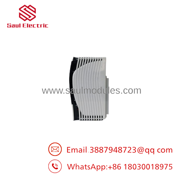
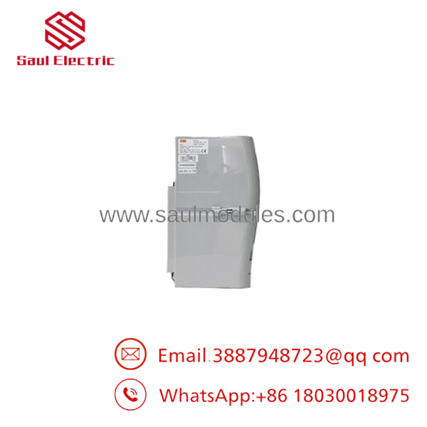
The ABB AI03 is a high-density, 8-channel analog input module developed exclusively for the Symphony® Plus and Harmony distributed control system (DCS) computing lines. This hardware acts as the primary sensory translation layer for process control loops, reading current and voltage measurements from field transmitters—such as pressure cells, flow sensors, and level indicators—and converting them into clean 16-bit digital values across the high-speed HN800 module bus.
Unlike lower-tier generic input arrays, the AI03 features complete galvanic isolation between its individual channels, a design that systematically dampens ground loops and contains catastrophic electrical field faults from propagating back into the main control rack processor. Its fast conversion update loop ensures precise tracking for complex, fast-acting closed-loop tuning schemes in high-consequence utility and heavy industrial manufacturing operations.
Installation & Configuration Guide
Stage 1: Pre-Installation Preparation (Estimated Time: 10 minutes)
- ⚠️ Safety First: Inform operations before isolating any instrumentation loop. Swapping an input card can cause upstream PID loops to drop to failsafe limits, potentially forcing valves to shut or heaters to trip. Secure associated interlocks inside the DCS software matrix.
- Tools Required: Grounded anti-static (ESD) wrist strap, small flat-blade terminal screwdriver, and a calibration-certified multimeter.
- Data Backup: Access the S+ Engineering or Composer development environment. Record the specific channel tuning constants, engineering unit spans (e.g., 0-100 psi), filter times, and block configuration tags assigned to this specific slot position.
Stage 2: Removing the Old Module (Estimated Time: 5 minutes)
- Affix your grounded ESD wrist strap to the bare cabinet grounding terminal stud.
- If the module base utilizes a separate removable terminal block assembly, unlatch the harness retaining clip carefully. Do not tug on individual loop wires.
- Press the upper and lower plastic module release tabs located on the faceplate assembly.
- Draw the AI03 module straight forward along its base guide slots to separate it from the backplane connector socket pins.
- ⚠️ Note: Do not rock or twist the module during extraction to prevent stress cracks on the multi-pin backplane board. Place the pulled card inside an anti-static shield bag.
Stage 3: Installing the New Module (Estimated Time: 10 minutes)
- Keep the replacement AI03 module inside its anti-static package until you are directly in front of the active rack slot.
- Check that the guide rails on the base mounting unit are clear of foreign matter.
- Align the module card edges with the slot tracks and slide the unit inward firmly until the retaining tabs lock onto the rack rim with an audible mechanical click.
- Re-engage the loop wiring terminal assembly block and secure its locking screw.
Stage 4: Power-On & Testing (Estimated Time: 15 minutes)
- The AI03 module automatically initializes and runs hardware checks via backplane power.
- Check the front LED cluster: The “R” (Ready) light should turn solid green. If the “F” (Fault) light turns steady red, a critical hardware fault or module address mapping conflict exists.
- Open your DCS engineering workstation to verify that the module’s communication status transitions to healthy.
- Use your multimeter to verify that a healthy 24 V DC loop power is feeding out to the instrument transmitters.
- Have a tech execute a quick physical validation check at a single field instrument node (e.g., bleeding pressure at a manifold) and verify that the corresponding input register value responds dynamically on the operator graphics display.
- ⚠️ Troubleshooting Note: If the “F” fault light stays illuminated after inserting the new unit, verify inside the engineering tool that the firmware profile baseline defined for that specific slot location matches the physical revision stamp found on the side sticker of the new module card.
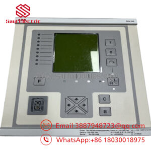
- AI03
Frequently Asked Questions (FAQ)
Does the module support hot-swapping under live rack power?
Yes, the Symphony Plus architecture natively supports hot-swapping for the module. You can physically pull a failing card and insert a new surplus spare without isolating power to the broader I/O rack or disrupting adjacent functional cards. However, remember that any instrumentation loops wired directly into this single card will drop offline instantly during the physical swap window.
Does this card supply loop power directly to 2-wire transmitters?
The module can be configured to work with either externally powered 4-wire transmitters or loop-powered 2-wire instruments. The exact delivery of the 24 V DC loop auxiliary supply to the field transmitter depends on how you configure the underlying base termination unit jumpers or external terminal cross-wiring patterns. Always consult your cabinet master schematic before landing wires.
What happens if an input transmitter fails or a wire breaks?
The incorporates intelligent wire-break and out-of-range sensor monitoring. If an instrument signal drops below 3.6 mA (or rises past 21.0 mA), the card registers an underflow/overflow error state, changes its internal channel health flag to “Bad,” and illuminates a channel-specific diagnostic code block. This allows the master DCS logic to safely dump associated control loops into manual or safe modes automatically.
Why is 16-bit resolution important for this class of analog inputs?
A 16-bit analog-to-digital converter (ADC) parses the incoming electrical signal into 65,536 distinct steps. This granularity allows the control software to resolve miniscule variations in process variables (such as slight pressure drops or fluid velocity shifts), resulting in more stable loop calculations and eliminating the measurement noise common in older 12-bit legacy cards.
How do I troubleshoot a single channel showing erratic, jumping values while others are stable?
First, check for field-side electrical interference. Disconnect the erratic field loop wires from the base termination unit and attach a stable milliamp current simulator box directly across the channel terminals. If the channel reads perfectly stable in your DCS graphics window while simulating, the fault lies in a damaged field wire shield, water entry inside the instrument conduit fitting, or a failing field transmitter device.


 Start Chat


