





Description
Key Technical Specifications
| Parameter | Value |
| System Slot Footprint | Occupies 1 single slot in a standard Module Mounting Unit (MMU) |
| Hosting System | ABB Bailey INFI 90 / Symphony Harmony |
| Companion Processors | IMMFP01, IMMFP02, IMMFP03 (Multi-Function Processor) |
| Feedback Interface Type | LVDT (Linear Variable Differential Transformer) demodulator |
| Auto-Tuning Capability | Integrated automatic demodulator gain calibration |
| Output Drive Profile | High-current analog drive for electro-hydraulic servo valves / I/H converters |
| Logic Voltage Requirements | +5 VDC (±5% @ 576 mA typical), +15 VDC (±5% @ 15 mA), −15 VDC (±5% @ 12 mA) |
| Field Power Drop | +24 VDC (±10% @ 335 mA typical supplied via the termination unit) |
| Hardware Configuration | Onboard structural jumpers and physical dipshunts |
| Ambient Temperature Rating | 0 to +70 °C (32 to 158 °F) operational limit |
| Enclosure Isolation | Standard open-card module configuration (IP00 base, fits IP20+ racks) |
Product Introduction
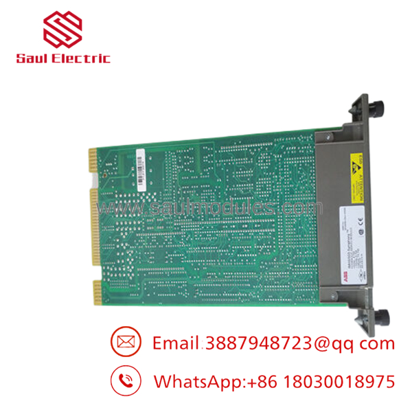
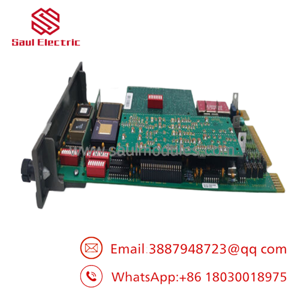
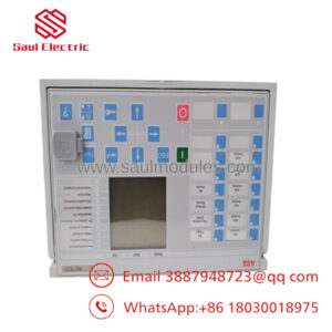
The ABB Bailey IMHSS03 is an intelligent Hydraulic Servo Module designed for precision valve positioning within the legacy INFI 90 and Symphony Harmony Distributed Control System (DCS) architectures. Acting as a high-speed, closed-loop bridge between the digital control logic of a Multi-Function Processor (such as the IMMFP02 or MFP03) and the analog reality of high-pressure hydraulic actuators, this module is an essential component for heavy industrial rotation systems. Its primary duty is regulating the high-current coil output signals that position electro-hydraulic servo valves and I/H converters, adjusting physical media delivery streams down to fractions of a millimeter.
The IMHSS03 features an integrated LVDT (Linear Variable Differential Transformer) feedback interface, which allows the module to form an independent, localized position loop away from the main processor’s traffic lines. When paired with an IMFCS01 Frequency Counter module (which tracks precise turbine shaft RPM via magnetic pick-ups), the system provides precise control over steam turbine throttle/governor valves, gas turbine fuel nozzles, and large inlet guide vanes. Additionally, the IMHSS03 introduces automatic demodulator gain tuning, a major performance update over older legacy IMHSS01 and IMHSS02 variants that minimizes setup times and eliminates the thermal loop drift common to purely manual tuning arrangements.
Technical Pitfall & Survival Guide
- The Backplane Dipshunt Power Surge
❗ Risk: Plugging or unplugging configuration dipshunts or option jumpers on the Module Mounting Unit (MMU) backplane or the card face while the rack power supply is energized. This live adjustments generate high-frequency logic bus transients that can corrupt the module’s non-volatile parameter layers or blow out the sensitive ±15V operational amplifiers.
- Avoidance: Always open the main power distribution breakers feeding the targeted MMU cabinet tier before shifting hardware links or sliding the module card along its guide rails. Verify all voltage drops are at absolute zero using a multimeter test at the backplane test pins.
- LVDT Phase Inversion and Oscillatory Runway
❗ Risk: Swapping the secondary winding return lines (S_1 and S_2) from the LVDT positioning sensor during field termination maintenance. Reversing these signal lines turns your target negative feedback loop into a destructive positive feedback loop, causing the module to drive the servo wide open or hard shut against its mechanical end-stops, risking mechanical damage or turbine overspeed trips.
- Avoidance: Before returning a re-wired or replaced valve assembly to service, perform a dry, un-pressurized stroke test. Manually watch the position feedback variables via the DCS console or a local loop tool to verify that an increase in control demand matches a positive increase in feedback displacement.
- The Function Code 55/150 Block Match Failure
❗ Risk: Dropping an IMHSS03 card into a slot previously populated by an older IMHSS01 unit without checking the configuration fields in Function Code 55 or 150. If the configuration parameters do not account for the automatic demodulator gain tuning offsets of the newer revision, the master MFP module will reject the tracking loop and flag a Configuration Mismatch error, disabling the automated loop.
- Avoidance: Use Composer or WinTools engineering workstations to audit your logic templates prior to hot-insertion. Update the block code to match the exact hardware revision footprint of the IMHSS03 to ensure proper communication upon system boot.
- IMHSS03
Troubleshooting Quick Reference
| Symptom | Possible Cause | Relevance to this Part | Quick Check Method | Recommendation |
| Module status LED turns solid red or displays a fault flash code | Watchdog timer timeout, internal RAM/ROM checksum failure, or loss of +5V logic rail. | ✅ High | Check the front edge diagnostic LEDs. Verify the voltage drops at the rack power backplane terminals. | If power is verified but the module stays locked in an internal fault state after a power cycle, the primary microprocessor board is damaged. Replace the module. |
| “LVDT Error” or feedback reading fluctuates erratically | Misaligned sensor core, broken field cable shield, or uncalibrated demodulator gain parameters. | ✅ High | Connect an oscilloscope across the LVDT excitation terminals to look for wave distortion. Verify the shield continuity. | Re-run the automated tuning sequence through Function Code 150. If noise persists, locate and repair broken ground links on the external signal cabling. |
| Valve fails to move despite active demand change from MFP | Blown +24V auxiliary fuse on the termination unit or open circuit in the servo coil. | ✅ High | Measure the loop current output directly at the field termination block pins using a series milliammeter. | If the module is outputting current but the valve remains stationary, check for mechanical binding on the servo pilot stage or an external hydraulic pressure failure. |
| “Module Missing” warning flagged on the host MFP node | Dirty edge connector contacts, bent backplane pins, or wrong module address settings. | 🟡 Medium | Extract the module card and inspect the gold-plated fingers on the rear connector interface. Check address dipswitch positions. | Clean the card contacts using an approved electronics cleaning solution. Straighten any bent pins inside the MMU slots before re-inserting the card. |
Frequently Asked Questions (FAQ)
Can the directly replace an older IMHSS01 or IMHSS02 module?
Yes. The is designed as a direct, backward-compatible replacement for both the IMHSS01 and IMHSS02 models. It drops into the same Module Mounting Unit (MMU) slot footprints and links up with the same termination units. However, it provides better thermal performance and includes an auto-tuning feature for the LVDT demodulator circuit.
What is the purpose of the auto-tuning feature on the ?
On legacy modules, matching the LVDT’s specific electrical output characteristics required manual adjustment of analog trim potentiometers. The handles this automatically through its digital logic platform, tuning its demodulator gain settings to match the stroke profile of the valve actuator, which reduces manual calibration errors and drift over time.
Does this module require an external power supply to run high-output servo coils?
The module uses standard low-voltage logic rails (+5V, ±15V) from the INFI 90 cabinet backplane for its internal computing blocks. To drive heavy hydraulic servo valve coils, it relies on an auxiliary +24 VDC source routed directly through its associated field termination unit, which provides the current needed to actuate the valves.
How are the module address and configuration properties established on this card?
The base node address and key operational properties are set using a physical array of jumpers and dipswitches located directly on the module’s printed circuit board (PCB), along with dipshunt settings on the matching termination unit. Fine-tuning of protection tolerances and gain curves is managed digitally via Function Codes 55 or 150 using your system’s DCS configuration software.
Why should our plant procure a New Surplus or Refurbished unit rather than modernizing the rack?
Turbine control retrofits can cost hundreds of thousands of dollars and require weeks of planned shutdown time for engineering, rewriting logic, and safety certification. Sourcing a New Surplus or fully tested Refurbished module allows maintenance teams to fix critical valve positioning issues immediately, maintaining system reliability without the high costs and downtime of a full system upgrade.


 Start Chat


