





Description
Key Technical Specifications
| Parameter | Specification Value |
|---|---|
| Protocol Compatibility | PROFIBUS DP-V0 and DP-V1 (Master Class 1) |
| Hardware Compatibility | AC 800M Processors (PM851 up to PM891 series) |
| Network Redundancy | Built-in master line redundancy (Dual ports: PROFIBUS A & B) |
| Data Transmission Speed | 9.6 kbps up to 12 Mbps (Auto-baud detection matching bus) |
| Maximum Slave Capacity | Up to 124 remote PROFIBUS slave nodes per master card |
| Current Draw (24 V DC) | Typical 260 mA from external 24 V DC supply rails |
| Power Dissipation | Max 6.2 W under peak data transmission loads |
| Connection Port Types | 2 x 9-pin D-sub female connectors |
| Galvanic Isolation | Standard functional isolation separating internal logic from bus line transceiver circuits |
| Physical Footprint | Single-width extension slot on specialized TP854 baseplate |
| LED Indicators | F (Fault), R (Run), RxA/RxB (Activity), PRIM (Primary), DUAL (Redundant pair link status) |
Product Introduction
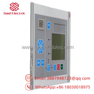
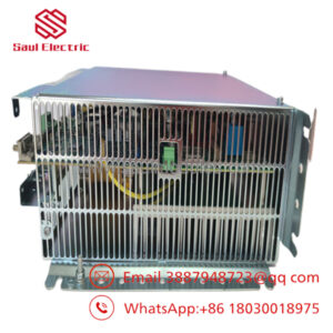
The ABB CI854AK01 (3BSE030220R1) is a high-performance PROFIBUS DP-V1 master interface kit engineered specifically for the AC 800M controller series within ABB System 800xA and Compact Product Suite deployment topologies. This hardware bundle functions as an open communications gateway, permitting industrial processing units to seamlessly supervise, read, and write diagnostic packages directly to remote I/O blocks (such as S800, S900, or third-party networks), variable speed motor drives, and smart smart-field instruments.
Unlike standard single-channel fieldbus connectors, the CI854AK01 features fully redundant physical transmission logic (utilizing independent PROFIBUS A and B sub-D pathways) to ensure continuous, high-availability monitoring loops inside high-reliability process lines. Operating under the class-1 master ruleset, the module delivers fast, cyclic I/O data processing (DP-V0) alongside comprehensive, asynchronous parameter read/writes (DP-V1) for complex asset management systems.
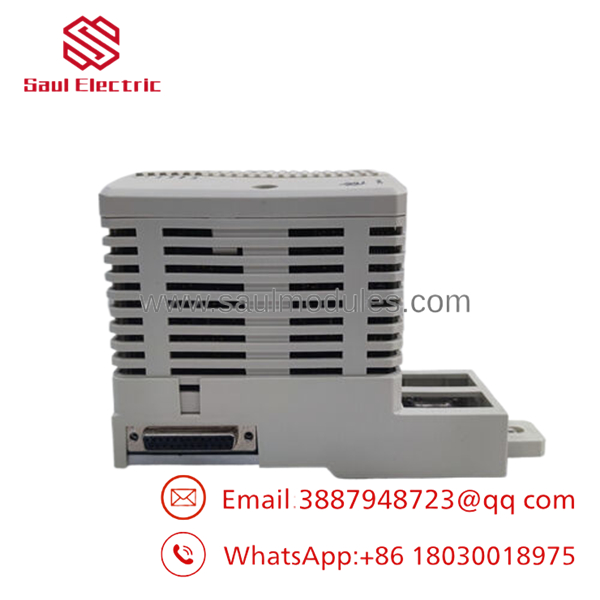
- CI854AK01 3BSE030220R1
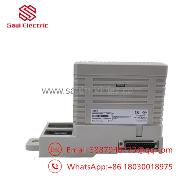
- CI854AK01 3BSE030220R1
Installation & Configuration Guide
Stage 1: Pre-Installation Preparation (Estimated Time: 15 minutes)
- ⚠️ Safety First: The introduction or removal of an active master module can alter the fieldbus bus impedance profile or drop whole drops of remote instruments, triggering emergency shutdown routines. Confirm that all local safety loops are decoupled before making connection changes.
- Tools Required: Grounded anti-static (ESD) wrist strap, small flat-blade terminal screwdriver, and an engineering terminal featuring the appropriate versions of Control Builder M or System 800xA Engineering suite.
- GSD Files: Gather any external Device Description (.GSD) profiles required for third-party instruments linked downstream of this master. Ensure these are compiled into the software device library prior to system download.
Stage 2: Mounting the Baseplate & Module (Estimated Time: 10 minutes)
- Affix your grounded ESD wrist strap to a verified metal grounding point inside the enclosure.
- If installing an entire system loop addition, mount the TP854 baseplate carrier onto the DIN rail track adjacent to the primary controller cluster, snapping the integrated interlocking bus slides firmly home.
- Align the CI854A module with the guiding grooves of the baseplate housing assembly.
- Press the module firmly straight back into the module receptor until the physical lock tabs fully click into position. Secure the top panel retaining screw.
Stage 3: Connecting the Physical PROFIBUS Network (Estimated Time: 10 minutes)
- Inspect your PROFIBUS cables. Ensure they are using high-quality purple type-A shielded twisted-pair physical cabling.
- Plug the primary trunk line connector directly into the lower port labeled
PROFIBUS A. - If running a redundant network backbone array, plug the secondary channel link into the lower port marked
PROFIBUS B. - Secure the D-sub retaining screws tightly.
- ⚠️ Termination Check: Ensure that the physical termination switch on the D-sub plug housing is flipped to the ON position only if this controller station represents the absolute start or end boundary node of the physical fieldbus run.
Stage 4: Commissioning & Functional Test (Estimated Time: 15 minutes)
- Turn on the 24 V DC power supply lines feeding the AC 800M cluster backplane.
- Watch the front diagnostic lights: The green
R(Run) indicator should illuminate steadily, while the redF(Fault) indicator should switch off after completing its self-check routine. - Inside Control Builder M, insert the CI854 hardware module node under the CPU controller path. Define the target network parameters (e.g., Baud rate, address indexes).
- Initiate a full project compile and perform a safe online application download to the controller.
- Confirm that the
RxA(andRxBif using redundant lines) lights begin to flicker amber rapidly, verifying normal cyclical token ring execution with your slave instruments.
Frequently Asked Questions (FAQ)
What is the distinction between the legacy CI854K01 and the newer CI854AK01 kit?
The “A” variant designated within the CI854AK01 part configuration represents an updated revision level containing modified internal board component routing designed to fulfill modern component environmental standards, such as RoHS compliance frameworks. The newer “A” unit serves as a form, fit, and functional drop-in replacement for the older non-A hardware variants.
Can I run a combination of DP-V0 and DP-V1 slave devices on the same network line?
Yes. The handles concurrent multiplexing routines. It can smoothly handle basic cyclic processing frames (DP-V0 data weights such as digital inputs/outputs) while simultaneously routing acyclic parameter adjustments or instrument diagnostics (DP-V1 profiles like calibration values or detailed fault logs) down the exact same physical cabling plant without data conflict.
How do I configure hardware redundancy using this specific kit model?
To achieve full system master-level line redundancy, you install two matching kits side-by-side onto their respective baseplate slots inside the controller assembly. You then configure them as a single redundant pair inside Control Builder M. Under normal operation, the designated “Primary” module coordinates active communication (indicated by a solid PRIM LED). If a fault occurs, control switches to the backup tracker card in milliseconds.
Does this kit package contain the required fieldbus termination elements?
No. The kit packages the primary processing module and its physical interlocking backplane component block. PROFIBUS termination routines must be activated on the physical 9-pin D-sub line plugs themselves, or via an external active network termination block terminal installed at the ends of your physical network bus segment.

 Start Chat


