





Description
Key Technical Specifications
| Parameter | Value |
| Brand | ABB |
| Model Number | DSAI133A |
| Global Product ID | 3BSE018290R1 |
| I/O Channels | 32 Single-Ended Analog Inputs |
| Resolution | 12-Bit (0 \dots 4095 units) |
| Current Signal Ranges | 0 \dots 20 mA, 4 \dots 20 mA (with external shunt resistors) |
| Voltage Signal Ranges | 0 \dots 10 V, 2 \dots 10 V |
| Galvanic Isolation | Group-isolated from the system backplane logic |
| Hardware Fit | S800 I/O Subrack / Advant Controller installations |
| Net Weight | 0.42 kg |
| Country of Origin | Sweden (SE) / Estonia (EE) |
Product Introduction
The ABB DSAI133A 3BSE018290R1 is a high-density, 32-channel analog input module functioning within ABB’s legacy Advant OCS and versatile S800 I/O distributed processing networks. Engineered to interface directly with diverse process sensors—such as flow meters, pressure transmitters, level sensors, and temperature indicators—this module digitizes incoming electrical loops with 12-bit analog-to-digital converter (ADC) precision.
By grouping 32 inputs onto a single space-saving card framework, the DSAI133A drastically reduces the required physical footprint inside automation cubicles. It incorporates built-in filtering networks to cancel high-frequency industrial noise and harmonics, delivering clean, fast, and repeatable data registers back to central processors via the subrack’s system bus.
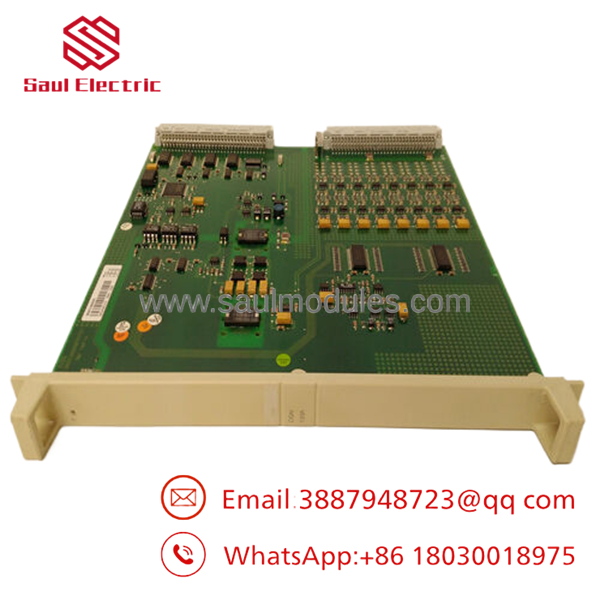
- DSAI133A 3BSE018290R1
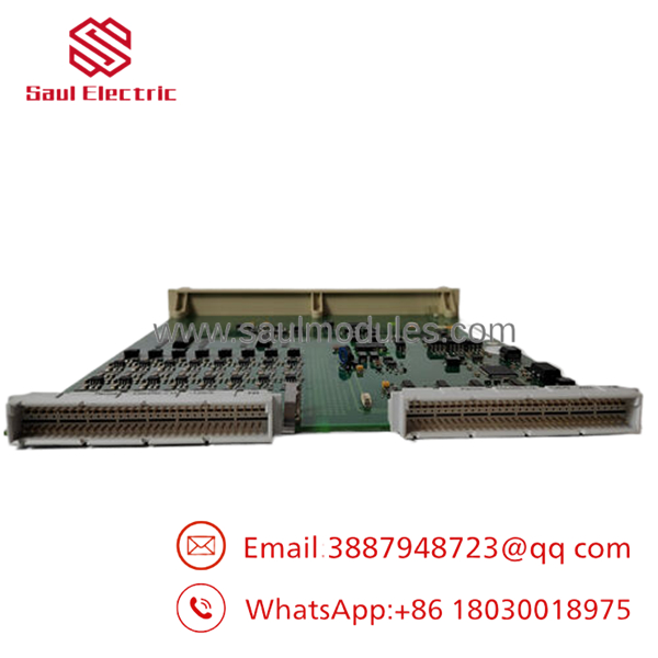
- DSAI133A 3BSE018290R1
Installation & Configuration Guide
1.Hardware Preparation & Shunt Settings:Estimated time: 5 mins.
Check the input signal requirements. If the field loop sensors operate on current loops (4 \dots 20 mA), verify that the corresponding external connection base units are fitted with the correct shunt resistor values (250\ \Omega typical).
Inspect the board pins and ensure your ESD protection grounding strap is securely clamped to the cabinet metal housing frame before taking the DSAI133A out of its anti-static shielding bag.
2.Card Slot Allocation & Seating:Estimated time: 10 mins.
Verify that the subrack slot matches the allocation configured inside your engineering software (e.g., Control Builder M or Advant station configurator). Switch off the terminal base loop excitation power.
Slide the module straight and level into the card guide tracks. Push firmly on the outer injection-molded locking tabs until the high-density backplane pins slide fully home. Fasten the integrated faceplate screws to ensure continuous chassis grounding contact.
3.Signal Loop Cable Termination:Estimated time: 15 mins.
Connect the pre-routed 32-channel terminal block umbilical plugs to the module’s companion termination base. Ensure that all unshielded field sensor cable pairs run through grounded shield bars immediately upon entry into the marshalling box.
Pre-Power Checklist:
- [ ] The card is locked tight into the subrack backplane connectors.
- [ ] Signal grounds are wired to avoid parasitic earth loops.
- [ ] All 24 V DC loop power circuits match the module’s input pin layouts.
4.System Check & Calibration Verification:Estimated time: 10 mins.
Turn on the subrack and sensor power breakers. Watch the board’s front-panel status LED panel:
- Run LED: Should switch to steady green, proving successful internal diagnostic checks.
- Fault LED: Must remain dark. If it flashes red, look for an unconfigured hardware slot identifier or an open field wire connection.
Simulate a known baseline voltage or current value (4 mA or 1 V) directly at a field junction block and check that the correct digital values register on the HMI workstation screen.
Frequently Asked Questions (FAQ)
Q: What is the main difference between the original DSAI133 and the upgraded ?
A: The “A” suffix denotes a production component update using components with higher thermal stability and enhanced electrical noise suppression. The is 100% form, fit, and functionally interchangeable with older DSAI133 models. It uses the exact same software database templates and connection setups.
A: No, the channels are single-ended and group-isolated from the system’s inner backplane logic rather than being individually channel-to-channel isolated. This means all 32 inputs share a common internal ground line. If your installation requires complete galvanic channel-to-channel isolation to prevent complex ground loops, you should use external signal isolation barriers between the field sensors and the module inputs.
Q: How does the module handle a broken field wire or dead sensor loop?
A: When configured for standard 4 \dots 20 mA or 2 \dots 10 V ranges, the module monitors the lower signal limits. If a wire breaks and the signal drops below roughly 2 mA or 0.5 V, the module flags an underflow condition. It passes an I/O channel error state to the controller, which can then trigger an open-circuit alarm on the operator’s display.
A: Yes, you can mix voltage and current signals across different channels on the same board. This is because the signal type configuration is determined by how the field wires are connected to the external termination terminal block (i.e., whether the current shunt resistor is inline or bypassed) and how the channels are set up in the controller’s I/O configuration software.



 Start Chat


