





Description
Key Technical Specifications
| Parameter | Specification |
| Part Number | 3BSE018292R1 |
| Number of Channels | 16, single-ended, non-isolated between channels |
| Resolution | 8 bits |
| Output Range | −10 V to +10 V, 0 to 20 mA, or 4 to 20 mA (via configuration) |
| Backplane Current Consumption | 5 V DC, typ. 130 mA; 24 V DC, typ. 150 mA |
| Isolation | Galvanic separation via optocouplers between bus and channels |
| Update Time | < 5 ms for all 16 channels |
| Operating Temperature | 0 to +55°C |
| Storage Temperature | −40 to +70°C |
| Form Factor | S100 I/O Rack format, standard slot width |
| Weight | 0.65 kg |
Product Introduction
The ABB DSAO130A (part number 3BSE018292R1) is a 16-channel analog output module designed for the legacy S100 I/O rack system, commonly deployed alongside MasterPiece 200 and Advant Controller 410/450 systems. It functions as the critical link between the digital control logic of the DCS backplane and physical field actuators, such as control valves, variable speed drives, and analog positioning elements. By providing 16 independent output paths, a single module handles dense signal arrays, maximizing slot efficiency in crowded control cabinets.
Engineered for highly reliable industrial service, the card features built-in galvanic isolation via optocouplers to protect the central processor rack from external electrical faults on the field loops. While newer systems leverage 12-bit or 16-bit resolutions, the 8-bit architecture of this module provides rapid, predictable update times under 5 ms across all channels, ensuring tight loop control for standard speed-matching and modulation applications. It remains a preferred choice for facilities keeping critical legacy automation systems running without the expense of a full system migration.
Troubleshooting Quick Reference
| Symptom | Possible Cause | Relevance to this Part | Quick Check Method | Recommendation |
| All channel outputs drop to 0 V or 0 mA | Lost 24 V DC external field power supply | ❌ Low | Measure for 24 V DC at the external distribution fuse or terminal strip feeding the card’s field side. | Replace blown field fuses or check the primary power supply before pulling the module. |
| Run LED is off; Fault LED is solid red | Internal hardware component failure / micro-controller lockup | ✅ High | Verify backplane voltage is exactly 5 V DC. If 5 V is present and resetting the rack fails to clear the fault, the card is dead. | Replace the DSAO130A module immediately. |
| Single channel output remains frozen or erratic | Blown output driver transistor on that specific channel | ✅ High | Change the output command in software from 0% to 100% and measure voltage directly across the module output pins with a Fluke 115 multimeter. | If the voltage does not track the software command but adjacent channels do, the module has physical hardware damage. Replace the module. |
| High signal noise or erratic positioning on field valves | Ground loop or shield connection breakdown | ❌ Low | Disconnect the field wiring harness from the card and check isolation between signal ground and chassis ground. | Ensure signal shields are tied to ground at a single point only; check for nearby high-voltage cable interference. |
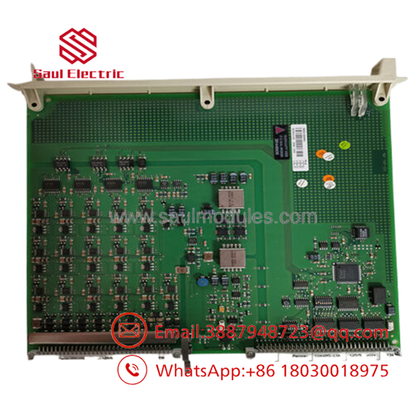
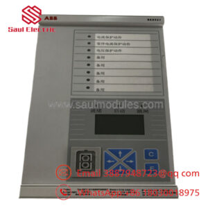
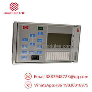
- DSAO130A
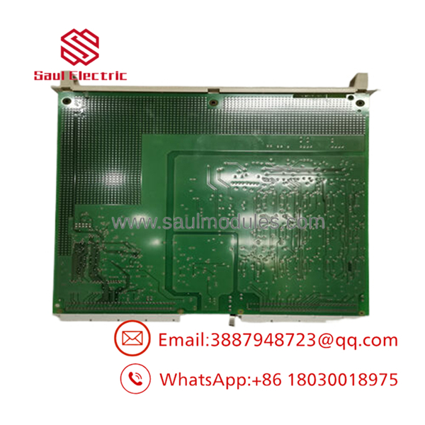
- DSAO130A
Frequently Asked Questions (FAQ)
Can I hot-swap this module while the process is running?
No, the S100 I/O rack architecture does not support true hot-swapping for standard cards. Pulling the module while the backplane is energized risks causing an electrical arc across the gold pins, which can fry the backplane bus transceiver or cause adjacent cards to drop off-line. Always power down the specific sub-rack before removing or inserting any card.
What is the exact difference between an 8-bit module like this and a 12-bit module?
It comes down to resolution step size. An 8-bit card divides the full signal range into 256 discrete steps (2^8). For a −10 V to +10 V range (a 20 V span), each step is roughly 78 mV. A 12-bit card gives you 4,096 steps (2^{12}), which means smaller, smoother increments. If your control valve requires hyper-precise micro-adjustments, an 8-bit card can feel a bit stepped. However, for general speed references and standard modulation loops, it works perfectly and updates across all channels significantly faster than heavy 12-bit filtering schemes.
How do I configure this module for voltage vs. current output?
Configuration is handled via physical jumpers or DIP switches located directly on the printed circuit board. You cannot change these settings purely through software. Before dropping the card into the slot, you must physically set the jumpers for each channel to match your field device requirements (e.g., setting a channel for 0 to 20 mA current loops instead of −10 V to +10 V signaling). Always mirror the layout of your old card exactly before inserting the replacement.
Is this a direct drop-in replacement for older versions without the “A” suffix?
Generally, yes. The “A” revision denotes minor component updates from the OEM to account for parts obsolescence on the board layout, but form, fit, and functional compatibility remain backward-compatible. However, if your existing system runs specialized, highly sensitive firmware versions, check your system documentation. As an engineering practice, verify the hardware revision matches your existing drawings before commissioning.
Why is a New Surplus unit cheaper than buying direct from the OEM?
New Surplus units come from cancelled integration projects, spare parts inventory liquidation, or climate-controlled facility storerooms that upgraded their platforms. The hardware is original, unused, and often in its factory box, but because it bypassed the traditional OEM channel distribution, we can pass the savings directly to you. Every surplus card we supply undergoes full electrical checkouts and is backed by our own 1-year warranty.

 Start Chat


