





Description
Product Introduction & Engineering Value
Having spent years in power generation facilities, I know that when a crowbar circuit fires unexpectedly or fails to trigger during a grid fault, your excitation converter takes the hit directly. The ABB GDC801B (3BHE024747R0101) acts as the dedicated gate driver card responsible for firing protective thyristor crowbar stacks in high-power MV drive assemblies and UNITROL excitation systems.
It handles the high-speed interface between the main controller’s optical commands and the physical firing gates of the crowbar thyristors. By dumping DC-link overvoltage transients in microseconds, the GDC801B prevents costly bridge rectifier punch-throughs and keeps large synchronous machine drives online through transient network spikes.
Technical Specifications
- Operating Input Voltage: 24 V DC auxiliary logic supply
- Signal Transmission: Fiber-optic input/output channel link for high noise immunity
- Trigger Response Time: Sub-microsecond gate firing pulse delivery
- Board Isolation: High-voltage galvanic isolation (520 VDC isolation rating)
- Operating Ambient Temperature: -40°C to +70°C (-40°F to 158°F)
- Form Factor & Dimensions: 37.6 cm x 14 cm x 7.5 cm open frame PCB chassis card
- Net Weight: 0.74 kg (1.63 lbs)
- Conformal Coating: Standard industrial atmospheric protection against conductive dust and moisture
Field Application & The “Trench” Experience
The Trench Story
A 150 MW hydro station experienced a sudden load rejection during grid switching. The main excitation system attempted to dump the rotor field energy into the discharge resistor, but the GDC801B board on converter channel 2 failed to output the gate firing pulses to the crowbar thyristors. The resulting DC-link overvoltage blew the main surge suppression fuses, tripping the entire unit off line.
Troubleshooting showed that the fiber-optic receiver port on the original GDC801B card had clouded due to long-term cabinet heat exposure, dropping optical signal strength below the trigger threshold. The electrical crew swapped in a pre-tested replacement GDC801B, blew out the optical fiber ends with filtered air, and re-ran the manual gate pulse test. The card fired cleanly, clearing the excitation trip and allowing the hydro turbine to re-synchronize to the grid that same afternoon.
Specific Niche Applications
- Hydro Power Plant Generator Excitation: Managing crowbar energy dissipation in UNITROL 6000/PEC800 automatic voltage regulators (AVR) during sudden load drops.
- Large Synchronous Motor Drives: Protecting medium-voltage VFD inverter bridges during supply network voltage sags.
- Pumped-Storage Facility Converters: Providing fast-acting overvoltage protection across high-power converter DC links.
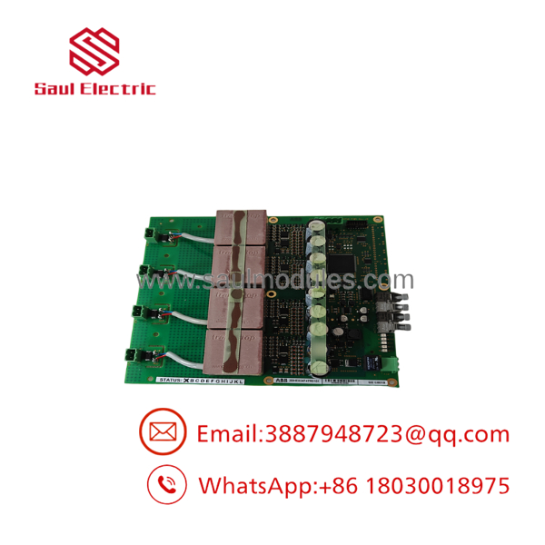
- GDC801B 3BHE024747R0101
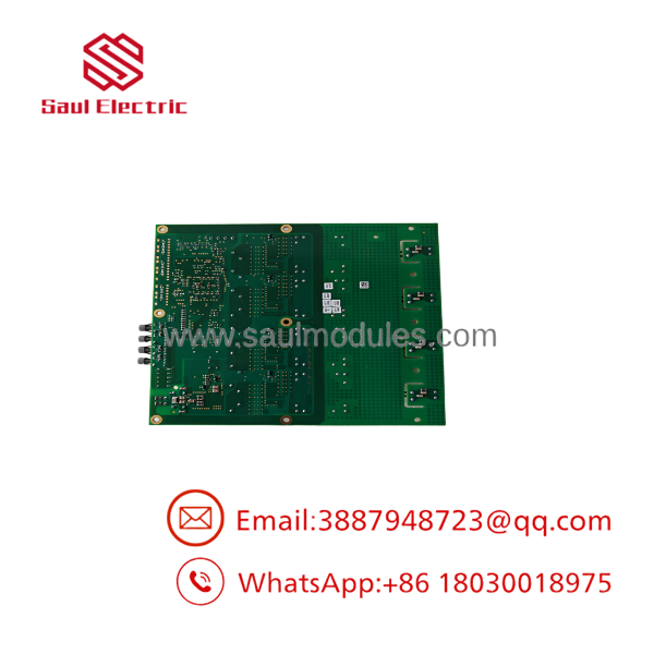
- 3BHE024747R0101
Transparency SOP: QA & Testing
- Phase 1 (Microscopic Inspection): We examine the board under high magnification to check for micro-fissures in solder joints, degraded electrolytic caps, or heat-discolored trace runs around the pulse transformers.
- Phase 2 (Bench Rail Power-Up): The is powered up on a 24V DC test bench. Onboard voltage regulators and internal power rails are probed to verify they operate within 1% of nominal factory specs.
- Phase 3 (Optocoupler & Gate Pulse Test): We feed high-frequency optical signals into the input channels and monitor the gate output pulses on a 200 MHz oscilloscope, checking pulse amplitude, rise time, and switching delays.
- Phase 4 (Thermal Chamber Cycle): The unit undergoes a 12-hour burn-in cycle inside a temperature-controlled environmental chamber, cycling between ambient and +65°C under active signal conditions to eliminate early-life failure risks.
The Veteran’s Tech Trap Guide
- ⚠️ Treat the Fiber Optics with Care: The optical ports on the board are sensitive to dust contamination and excessive bend radius on the fiber cables. Always inspect the optical tips with a scope before plugging them in. A dirty fiber lens can cause missed trigger pulses.
- PRO TIP: Do Not Overtighten Board Standoffs. When mounting this card into the chassis rack, hand-torque the mounting screws. Over-torquing can flex the PCB layer stack, creating micro-fractures in internal power plane layers that show up later as intermittent faults under heat expansion.
- ⚠️ Discharge the DC Link First: Before removing or replacing a card in a power converter cabinet, verify with a calibrated meter that the main DC-link capacitors are completely discharged below 50 V. High residual bus voltage can destroy the replacement card’s gate circuit upon insertion.
Dynamic FAQ
Q: Is the (3BHE024747R0101) directly interchangeable with the GDC801A? A: In most ABB PEC800 and UNITROL applications, the is a direct hardware drop-in for the earlier GDC801A revision. However, you should always check the converter firmware release notes to ensure gate timing parameters remain identical.
Q: Does replacing the board require flashing software or firmware? A: No. The is a dedicated hardware interface board. Firmware resides on the main controller CPU board, so no software loading is necessary after physical replacement.
Q: What indicates that the crowbar card has failed? A: Common symptoms include persistent “Crowbar Fault” or “DC Link Overvoltage” alarms on the AVR operator panel, missing gate pulse indications during commissioning diagnostic routines, or unlit power status LEDs on the card.
Q: Are your surplus units fully tested before dispatch? A: Yes. Every module in our inventory undergoes visual inspection, power rail validation, optical pulse verification, and thermal testing before shipment. All units include a 1-year warranty.




 Start Chat


