





Description
Key Technical Specifications
| Parameter | Value |
| Core Protection Platform | ABB Relion 615 Series (Standard Configuration Base) |
| Auxiliary Supply Range | 24 to 240 V AC / 24 to 240 V DC (50/60 Hz frequency matrix) |
| Continuous Load Threshold | Up to 50 A continuous monitoring throughput |
| Data Sampling Architecture | 32-bit DSP combined with ARM dual-core real-time logic processing |
| Communication Protocols | Modbus RTU, Profibus DP, and native Ethernet/IP or IEC 61850 |
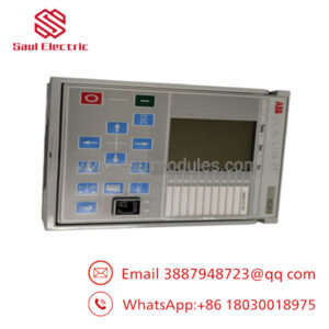
| Physical Housing Concept | 1/2 frame width withdrawable-unit mechanical design |
| Mechanical Protection | IP20 enclosure isolation rating |
| Outer Outline Envelope | 100 mm (W) x 200 mm (H) x 150 mm (D) |
| Net Weight | Approximately 0.50 kg |
| Environmental Operational Range | −20 to +60 °C continuous service |
| Compliance Matrix | Meets or exceeds IEC 61439-1, IEC 60204-1, and UL 508 engineering rules |
Product Introduction
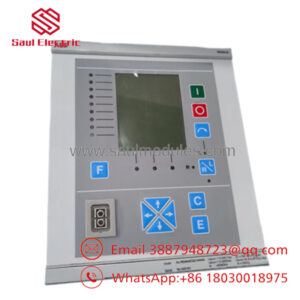
The ABB HBFFAEAGNBA1BAA11G is a high-reliability, multi-functional feeder protection and control relay belonging to the specialized Relion 615 series (REF615 framework). Engineered specifically for utility substations and dense industrial power systems, this compact unit monitors radial, looped, or meshed distribution networks to deliver precise overcurrent, overvoltage, undervoltage, and earth-fault protection. By marrying high-speed dual-core processing with a 24 to 240 V AC/DC wide-range auxiliary power stage, it safely monitors continuous operational currents up to 50 A while remaining immune to grid-side transient events.
Industrial networks employ this module to avoid catastrophic damage across large-scale motor applications, main distribution transformers, and local generation clusters. The HBFFAEAGNBA1BAA11G utilizes a distinct withdrawable mechanical design that speeds up physical field maintenance routines and minimizes downtime during unit testing sequences. Supporting multiple core bus systems, including IEC 61850 and Modbus RTU, it integrates into centralized SCADA platforms, letting plant engineers track analog measurements and verify fault isolation sequences in real time.
Technical Pitfall & Survival Guide
- The CT Secondary Open-Circuit Disaster
❗ Risk: Removing or separating the relay unit from its housing socket while the current transformer (CT) primary circuits are under load without checking that the CT shorting bars have closed correctly. An open-circuit CT secondary generates lethal kilovolt spikes that will arc across the housing and destroy the internal input sampling circuits.
- Avoidance: Even though the REF615 series features a withdrawable design with built-in automatic shorting mechanisms, always manually check that the CT shorting blocks are engaged at the terminal strip before pulling the relay module forward out of its cradle. Double-check your circuit pathways using a clamp meter.
- The Software Configuration Matrix Lockout
❗ Risk: Expecting the relay to process protection steps out of the box without running mapping steps through PCM600 software. The exact hardware alphanumeric code strings determine specific default I/O allocations; if your application file layout does not perfectly match the internal signal matrix variables, the unit will throw a terminal config fault and lock out the main breaker.
- Avoidance: Before pulling the damaged unit off the grid line, connect via PCM600 and pull a full backup of the parameter settings, protection thresholds, and custom logic curves. Write the configuration straight onto the replacement unit before sliding it into the active rack frame.
- Control Rail Sag Tracking Failures
❗ Risk: Powering the wide-range auxiliary input card via a noisy DC line that shares power paths with heavy inductive trip-coils or pneumatic line valves. High inrush demands will drag the voltage drop below the processing threshold, forcing the relay into an instantaneous cold-start sequence exactly when a grid fault needs clearing.
- Avoidance: Run a separate, clean, fused instrument power line to feed the relay’s auxiliary logic ports. I watched a maintenance team wire an auxiliary supply loop straight onto a high-current breaker trip rail; every time a heavy fault occurred down the line, the voltage sagged just enough to reboot the relay, causing it to miss the trip timing window and forcing upstream protection to trip out the whole sub-station plant. Use isolated instrument drops.
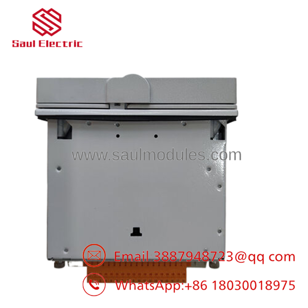
- HBFFAEAGNBA1BAA11G
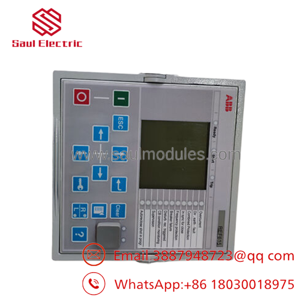
- HBFFAEAGNBA1BAA11G
Troubleshooting Quick Reference
| Symptom | Possible Cause | Relevance to this Part | Quick Check Method | Recommendation |
| Onboard display and diagnostic LEDs stay completely dark | Auxiliary control voltage missing, incorrect pin allocation, or blown input fuse. | ✅ High | Measure voltage directly across terminals X100:1 and X100:2 with a multimeter. Verify it reads between 24 and 240 V. | If supply voltage is present at the connector but the screen remains dead, the internal switching power card is failed. Replace the relay module. |
| “IRF” (Internal Relay Fault) Red indicator illuminated | Watchdog timer timeout, internal memory block checksum error, or component failure. | ✅ High | Establish an active communication link using PCM600 through the front optical/RJ45 port. Download the system event log file. | If the log confirms an internal RAM/ROM verification or ADC fault that stays active after a cold power cycle, hardware replacement is required. |
| SCADA reports “Communication Loss” with the relay | Misconfigured station bus node identification number, incorrect baud rate, or bad cable termination. | ❌ Low | Check the green TX/RX LEDs on the rear Ethernet or serial option ports. Run a local ping test down the line. | The issue is usually a broken trunk line or duplicate node addresses inside the master SCADA routing tables rather than a faulty relay. |
| “Trip” light triggers but main breaker remains closed | Blown interlock circuit fuse or mechanical binding on the breaker trip coil actuator. | ❌ Low | Measure the voltage pulse across the relay’s binary output terminals during a manual test sequence injection. | If the relay close contacts switch correctly but the breaker fails to move, look for an open trip-coil circuit or mechanical binding down the breaker rail. |
Frequently Asked Questions (FAQ)
What do the specific characters inside the model string “HBFFAEAGNBA1BAA11G” specify?
This code dictates the precise factory hardware profile of the REF615 module. It specifies the specific wide-range auxiliary supply card variant (24–240 V AC/DC), the specific analogue input card channels (CT/VT sensor configurations), the binary digital I/O layout, and the installed communication interface protocols. You must match this full exact code string to guarantee the replacement card drops into your existing wiring framework without needing configuration rewrites.
Is it possible to swap the internal chassis block of this relay without unwiring the rear terminal pins?
Yes, this is one of the main benefits of the REF615 series withdrawable design. The main processing module and internal cards slide out forward from the outer case envelope. The rear terminal wiring blocks stay connected to the cabinet frame, letting you complete an internal chassis replacement in minutes without labeling or landing dozens of individual wires.
Does this unit ship with custom protection curves pre-programmed into the memory chip?
No. Sourcing a New Surplus relay gives you a clean unit containing default factory protection curves and basic functional templates. You must use ABB’s PCM600 software platform to load your plant’s specific protection coordination profiles, coordinate pick-up currents, and set precise time-delay parameters before deploying the unit on a live grid.
Why should our procurement team source a New Surplus unit instead of a standard factory repair?
Lead time is the deciding factor. Sourcing direct factory production components can take weeks or months depending on build queues. Our New Surplus units are real physical inventory ready to ship immediately, letting you replace a damaged unit, clear an internal relay fault (IRF) warning, and restore full protection parameters to your substation without extended downtime.
Can this specific unit interface with modern IEC 61850 substation automation architectures?
Yes. The REF615 platform natively supports IEC 61850 standards for substation communication, including high-speed horizontal GOOSE messaging. This configuration allows the HBFFAEAGNBA1BAA11G to communicate directly with other Relion relays and upstream station controllers over an Ethernet backbone without needing intermediate protocol converters.

 Start Chat


