





Description
Key Technical Specifications
| Parameter | Value |
| Supply Voltage | 24 V DC (+20%, −15% per ripple tolerances) |
| Number of Inputs | 4 independent channels |
| Signal Input Range | ±10 V, 0 to 10 V, ±20 mA, 4 to 20 mA (Hardware Configurable) |
| Analog-to-Digital Resolution | 12-bit binary plus sign |
| System Bus Architecture | Integrated CS31 fieldbus interface |
| Node Addressing Range | Configurable via rotary switches (Address 0 to 60) |
| Galvanic Isolation | System-to-channel optical isolation barrier |
| Mounting Orientation | Vertical or horizontal on 35mm DIN rail |
| Enclosure Type | IP20 protected plastic shell housing |
| Operating Temperature | 0 to +55 °C natural convection environment |
Product Introduction
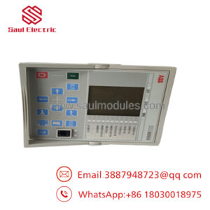
The ABB ICSA04B5 (FPR3341501R1042) is a remote analog input module engineered for the legacy Advant Controller 31 (AC31) and Procontic Series 90 PLC architectures. Functioning as a decentralized I/O node, this module reads up to four separate analog voltage or current channels directly from field transmitters—such as weight sensors, pressure cells, or flow monitors—and transmits the processed data back to the central master controller via the high-speed twisted-pair CS31 system bus. This decentralized topology reduces extensive field-to-control-room wiring runs, lowering installation costs and protecting against signal attenuation over long physical distances.
This module is designed for field-level ruggedness and contains a 12-bit bipolar analog-to-digital converter that maintains precise tracking even under shifting thermal conditions. The ICSA04B5 features complete galvanic optical isolation between the field inputs and the core CS31 communication bus. This electrical isolation prevents ground loops and inductive surges from migrating across the shared network line, ensuring that a localized fault at a remote sensor station cannot crash or damage the upstream master CPU rack.
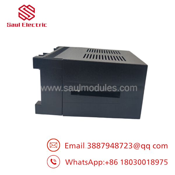
- ICSA04B5 FPR3341501R1042
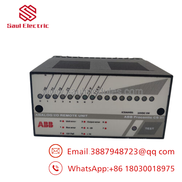
- ICSA04B5 FPR3341501R1042
Technical Pitfall & Survival Guide
- The Address Switch Collision Lock
❗ Risk: Forgetting to configure the mechanical rotary or DIP switches to match the exact hardware address mapped in your master PLC program. Setting twin modules to the identical node address will cause a data collision on the CS31 bus, causing both units to alternate dropouts and throwing the master controller into a communication failure loop.
- Avoidance: Before sliding the replacement module onto the rail, examine the side or face of the old unit. Use a small screwdriver to set the physical address dials on the new ICSA04B5 to mirror the exact position of the original module.
- The Current Loop Burnout Overlook
❗ Risk: Wiring a 4-20 mA current loop into a channel that is physically jumpered or configured for a 0-10 V voltage input signal. Sourcing high loop current into a voltage-mode configuration will overheat the input scaling resistors, permanently damaging that specific analog input channel.
- Avoidance: Check your internal jumper or terminal connection matrix according to your site schematic before connecting active signal wires. I watched an instrument technician swap one of these modules in a hurry during a midnight shutdown; they skipped matching the input mode links, connected a 24 V powered 2-wire loop, and fried the input stage on channel one the instant the main power came back online. Match the jumpers every time.
- Floating Shield Ground Induction Noise
❗ Risk: Leaving the analog signal cable shields ungrounded or grounding them at both ends of the cable run. This creates local ground loops that introduce massive high-frequency noise spikes into the 12-bit converter, causing your system values to drift or jump sporadically.
- Avoidance: Always strip and terminate the cable shield ground at one single point—ideally at the central marshalling panel ground bar. Ensure the shield jacket is completely insulated throughout the rest of the cable run to prevent accidental grounding contacts.
Troubleshooting Quick Reference
| Symptom | Possible Cause | Relevance to this Part | Quick Check Method | Recommendation |
| “Power” LED is dark; system is powered up | Auxiliary 24 V DC missing or reversed polarity wiring. | ✅ High | Measure voltage directly across the L+ and M supply terminals with a digital multimeter. | If 24 V DC is verified at the screw terminals but the power indicator remains dark, the module’s internal regulator has failed. Swap out the unit. |
| “Bus” LED is flashing red | Address mismatch, broken CS31 network wire, or missing terminating resistor. | 🟡 Medium | Verify the physical address dials on the module face match your PLC software configurations. Check line continuity on the twisted-pair network. | If the physical dials match the program map and adjacent nodes are working correctly, verify that a 120-ohm terminating resistor is seated at the end of the physical bus run. |
| Analog values read maximum value continuously | Open-circuit fault on a 4-20 mA input loop or failed input channel component. | 🟡 Medium | Disconnect the field loop wires. Use a process loop calibrator to inject a steady 12 mA signal directly into the module terminals. | If the value reads correctly during local injection, the problem lies in the field wiring or the transmitter. If the reading stays saturated, that channel’s analog-to-digital converter circuit is blown. |
| “Err” LED stays solid red | Hardware diagnostic failure or internal RAM checksum error on boot. | ✅ High | Cycle the primary 24 V DC input power supply off and on to initiate a fresh system self-test. | If the solid red error light returns immediately after the reboot sequence, the internal processing logic is compromised. Replace the module. |
Frequently Asked Questions (FAQ)
Can I hot-swap the ICSA04B5 module while the CS31 fieldbus is live and communicating?
No. The legacy AC31/ system architecture does not support hot-swapping remote I/O nodes. Removing or inserting the module’s terminal blocks while the network is powered can induce inductive spikes across the shared communication bus, which risks interrupting the signals of adjacent nodes or causing the master PLC CPU to drop into a fault halt state.
How do I switch individual input channels between voltage mode and current loop mode?
Configuring the signal mode on the requires a combination of physical terminal assignment variations (or internal layout jumper links) and matching parameter definitions inside your master programming software. Check your original system documentation or wiring schematic to ensure both the physical wire points and software variables match your field transmitter type.
Is this module compatible with newer AC500 series PLC systems?
The is built around the legacy fieldbus protocol. It can interface with newer AC500 series PLCs only if the modern CPU is equipped with a dedicated communication interface module or an equivalent legacy bus master coupler. If your new platform does not feature a physical interface port, the module cannot communicate natively.
What is the significance of the “FPR3341501R1042” number versus the “” code?
Both numbers identify the exact same physical component. FPR3341501R1042 is the unique, factory-level internal product code used by ABB’s global parts network for precise manufacturing tracking and procurement, while is the functional model designation stamped on the front faceplate. Ordering using either reference ensures you get a direct-fit replacement part.
Why should our site order a New Surplus unit instead of modernizing the full I/O rack?
The deciding factor is the high cost and extended downtime of a full system modernization. Upgrading a legacy system requires mounting new hardware, running new communication cables, and rewriting and validating legacy code logic. Sourcing a New Surplus module provides an immediate, drop-in solution that restores your analog loops in minutes without the engineering overhead of a full upgrade project.


 Start Chat


