





Description
Key Technical Specifications
| Parameter | Value |
| Core Control Platform | ABB AMC-3 / AMC-33 (Application & Motor Control Boards) |
| Drive System Compatibility | ACS6000 Medium Voltage AC Drive Systems |
| Input Signal Type | Absolute position Gray code (parallel or serial configuration) |
| Field Interface Voltage | 24 VDC |
| Master Communication | Optical DDCS link (1 Tx Sender, 1 Rx Receiver) |
| Auxiliary Signal Outputs | Analog speed monitoring signals & pulse output capability (interfaces with NTAC) |
| Fault Protection | Inherent single-bit transition error detection via Gray code logic |
| Physical Layout | Open PCB module for cabinet chassis mounting |
| Weight | Approximately 1.0 kg (2.2 lbs) |
| Operating Temperature | 0 to +55 °C typical industrial control environment |
Product Introduction
The ABB LDGRB-01 (part number 3BSE013177R1) is a highly specialized Gray-coded absolute encoder interface board, primarily deployed within ABB’s ACS6000 medium-voltage drive ecosystems. Its main responsibility is to translate high-speed, absolute rotor position data from field-mounted encoders into a format readable by the main Application & Motor Control (AMC-3 or AMC-33) processors. Because massive industrial drives require extremely precise phase-angle data to safely fire power semiconductor modules, the LDGRB-01 utilizes Gray code logic—where only one data bit changes between successive positions. This eliminates the catastrophic reading glitches common with standard binary encoders during rapid shaft acceleration.
This board serves as the critical bridge between the high-voltage physical motor environment and the noise-sensitive digital control rack. Field encoder signals arrive via a rugged 24V parallel or serial electrical interface. The LDGRB-01 processes this data and transmits it upstream to the AMC platform over a high-speed optical DDCS (Distributed Drives Communication System) fiber link. This fiber optic barrier provides absolute galvanic isolation, ensuring that massive voltage spikes or magnetic interference from the drive side cannot ride the ground line and corrupt the main controller. Additionally, the LDGRB-01 can loop processed analog signals out to local speed monitoring dials or NTAC pulse encoder interfaces for secondary DCS tracking.
Technical Pitfall & Survival Guide
- The Parallel Bit-Drop Commutation Fault
❗ Risk: In a 24V parallel Gray code setup, a single broken wire or corroded pin in the field cable will freeze one bit of the position data. The LDGRB-01 will transmit physically impossible phase angles to the AMC board, forcing the ACS6000 into a violent commutation fault or overcurrent trip the moment the motor attempts to rotate.
- Avoidance: Before condemning the LDGRB-01 board, disconnect the encoder harness and perform a pin-to-pin continuity check on every single parallel data line back to the motor terminal box. Use an oscilloscope or fast-acting multimeter to verify that the field 24V pulses are actually arriving at the board’s terminal block during slow manual shaft rotation.
- DDCS Fiber Optic Contamination
❗ Risk: The DDCS optical Tx/Rx ports on the are highly sensitive to microscopic dust. Leaving the transmitter or receiver ports uncovered during cabinet maintenance, or accidentally smudging the tip of the fiber cable with an oily glove, will attenuate the light signal. This causes dropped data packets, resulting in “Speed Feedback Loss” alarms and immediate drive shutdowns.
- Avoidance: Never remove the plastic dust caps from the optical ports until the exact second you are seating the fiber connectors. If the drive is throwing intermittent DDCS communication errors, use an optical-grade lint-free swab and 99% isopropyl alcohol to clean the transceiver lenses and cable tips before replacing the board.
- Tx / Rx Cross-Wiring Lockout
❗ Risk: Swapping the Transmit (Tx) and Receive (Rx) fiber optic lines when installing a replacement board. The AMC-33 controller will fail to establish a handshake on boot, leaving the drive locked out with a hard DDCS link failure.
- Avoidance: Modern ABB fiber links are often color-coded (gray and blue), but legacy harnesses fade over time. Always physically label the field fibers as “Tx” and “Rx” using tape tags prior to unplugging them from the defective unit. The Tx port on the must route to the Rx port on the AMC board, and vice versa.
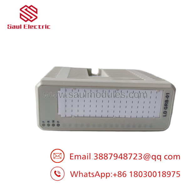
- 3BSE013177R1
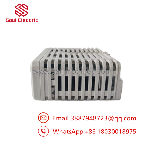
- 3BSE013177R1
Troubleshooting Quick Reference
| Symptom | Possible Cause | Relevance to this Part | Quick Check Method | Recommendation |
| Drive trips on “Position / Speed Feedback Loss” | Broken fiber optic cable, dirty DDCS port, or failed optical transceiver. | ✅ High | Unplug the fiber at the AMC board and check for a visible red light pulse coming from the Tx line during power-up. | If the Tx port on the is completely dark despite the board having 24V logic power, the optical transceiver has failed. Replace the module. |
| Erratic rotor position readings during low-speed jog | Loose wire on one of the 24V parallel input pins, or a damaged field encoder glass disk. | ✅ High | Scope the input terminal block on the to verify a clean 24V square wave on all active channels during rotation. | If all signals arrive cleanly from the field but the drive still calculates jumping phase angles, the board’s internal processing block is compromised. |
| Analog speed monitor instrument reads zero | Blown analog output channel on the or an open circuit in the meter loop. | 🟡 Medium | Measure the voltage directly across the analog output terminals on the with a multimeter. | If the drive operates normally but the analog output is dead at the terminals, you can either replace the board or rely on digital speed tracking via the main DCS. |
Frequently Asked Questions (FAQ)
What is the primary advantage of using Gray code over standard binary on this board?
In Gray code, only one single bit of data changes state between any two successive physical rotor positions. This prevents “glitches” or massive reading errors that can occur in standard binary if multiple mechanical/optical switches change state at slightly different micro-intervals, ensuring smooth and safe phase-angle calculation for the high-power drive.
Can the operate without the optical DDCS connection?
No. While it can theoretically output local analog signals independently, its primary function is to serve as the absolute position feedback node for the AMC-3 or AMC-33 control platform. The ACS6000 drive will not clear its start permissives without an active, healthy DDCS optical handshake with this board.
Is it necessary to calibrate the board after replacement?
The board itself is a hardware interface and does not require complex internal tuning or software flashing. However, whenever you replace the or the physical motor encoder, you must perform an absolute rotor position offset run (often called an ID Run or commutation calibration) from the main drive console to resynchronize the mechanical zero point with the electrical software model.
Does the provide power to the external field encoder?
The board facilitates the 24 VDC electrical interface, but you must ensure your system’s power distribution is correctly wired to supply the required excitation voltage to the encoder itself. Check your specific cabinet schematics to verify if the 24V is sourced from the board’s auxiliary pins or from an external cabinet power supply.
Why should our facility order a New Surplus instead of waiting for factory repair?
Medium voltage drives like the ACS6000 run critical, high-revenue processes (such as mine hoists, compressors, or rolling mills). A failed encoder board will halt the entire process train. New Surplus inventory bypasses extended OEM factory lead times, allowing you to get a replacement board on-site within days to clear the communication fault and restore drive operation immediately.


 Start Chat


