





Description
Key Technical Specifications
| Parameter | Value |
| Model Designation | NTCL01 / NTCL01R |
| Alternate Part Code | 6636997L1 / PNTCL01 |
| Module Compatibility | INNIS01 / INNIS11 (Network Interface Slave), INLIM03 (Loop Interface Module) |
| Network Interface | INFI-NET / Plant Loop / Superloop (Cnet in Symphony Plus) |
| Power Requirements | 24 V DC (19.7 mA maximum, 15.8 mA typical) |
| Overcurrent Protection | Onboard fuse for 24 V DC circuit protection |
| Physical Interfaces | BNC connectors (coaxial) and terminal strips (twinaxial) |
| Operating Temperature | 0 to +70°C (32 to 158°F) |
| Relative Humidity | 5% to 90% non-condensing (up to 55°C) |
| Dimensions | 236.2 mm (H) x 221.0 mm (W) x 96.5 mm (D) |
| Net Weight | 0.48 kg (1.06 lbs) |
Product Introduction
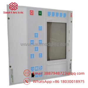
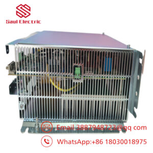
The ABB NTCL01 is an INFI-Net Communication Link Termination Unit designed for the legacy Bailey INFI 90, Network 90, and modern Symphony Plus rack-based systems. It serves as the physical termination point for the INNIS01/INNIS11 Network Interface Slave module or the INLIM03 Loop Interface Module. By establishing a clean, impedance-matched termination, the NTCL01 ensures high-integrity data transfer across the central industrial network loop.
Featuring onboard selection jumpers, the NTCL01 offers flexible physical layer adaptation, allowing system integrators to utilize either twinaxial or coaxial cabling to form the communication ring. Its integrated 24 V DC circuit is protected by a dedicated fuse, preventing localized line faults from taking down adjacent modules inside the Field Termination Panel (NFTP01).
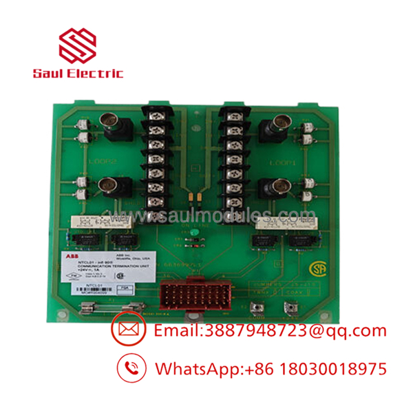
- NTCL01
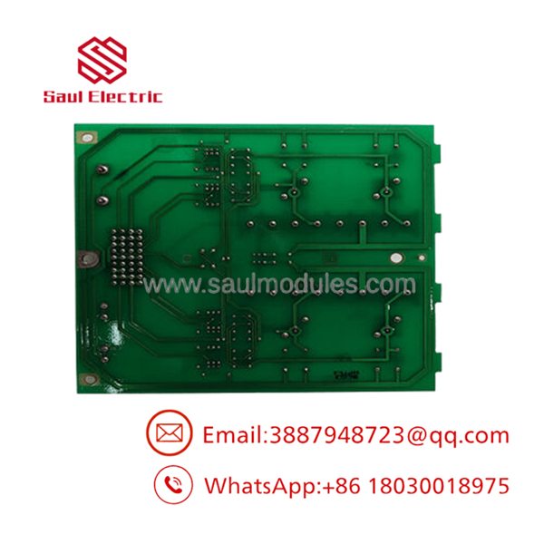
- NTCL01
Installation & Configuration Guide
Stage 1: Pre-Installation Preparation
- Estimated Time: 15 minutes
- ⚠️ Safety First: Notify the operations desk of network disruption, as interrupting the INFI-NET loop can cause slave consoles to lose communication with the Process Control Units (PCUs). Verify that the system is configured in a redundant ring so that breaking this node’s loop does not crash the entire control network.
- Tools Required: ESD grounded wrist strap, standard flathead screwdriver, PH2 crosshead screwdriver, digital multimeter.
- Data Backup: Document the physical cabling routing (which coax/twinax goes to the incoming loop versus outgoing loop). Photograph the jumper block settings on the existing board before removal.
Stage 2: Removing the Old Module
- Estimated Time: 10 minutes
- Steps:
- Attach your ESD grounding wrist strap to an unpainted metal surface on the cabinet frame.
- Disconnect the 24 V DC power feed connector from the termination unit.
- Carefully disconnect the BNC coaxial connectors or unscrew the twinaxial terminal connections. Label each cable as “IN” or “OUT” to avoid loop-back errors.
- Unplug the NKLS or NKPL adapter cable running from the termination unit to the slave interface module (INNIS01/INLIM03).
- Loosen the two mounting screws and one grounding screw holding the PCB to the NFTP01 Field Termination Panel, then lift the board out.
Stage 3: Installing the New Module
- Estimated Time: 15 minutes
- Steps:
- Set the new on an ESD-safe workspace.
- Configuration Clone (Critical step): Inspect the jumper configurations on the new board and align them with the old board’s settings.
- Jumper Configuration: Ensure jumpers are positioned correctly to match your cable impedance. (Set to Coaxial or Twinaxial mode based on your field cabling topology).
- Slide the board onto the NFTP01 panel mounting guides.
- Securely tighten the two mounting screws and the essential chassis ground screw.
- Reconnect the NKLS/NKPL interface adapter cable back to the respective INNIS/INLIM module.
- Securely attach the twinaxial terminal wires or twist-lock the BNC coaxial cables to their designated ports.
- Self-Checklist:
- [ ] Ground screw tightened down securely to panel frame
- [ ] Cable selection jumpers set to match physical cabling medium (coax vs. twinax)
- [ ] All network cable connections are tight and locked
Stage 4: Power-On & Testing
- Estimated Time: 10 minutes
- Pre-Power Check: Measure the incoming DC voltage on the power lines; it must register within the 24 V DC (\pm10%) operating range.
- Power-On Steps:
- Plug in the 24 V DC power connector.
- Verify that the system does not flag a local power supply fault. If the unit fails to initialize, check the onboard fuse.
- Check the status LEDs of the connected INNIS01 or INLIM03 interface module. The module should transition from initialization states to its active operational state.
- Run a loop diagnostic from the system console to verify that the node is sending and receiving tokens across the INFI-NET loop without packet CRC errors.
- ⚠️ Troubleshooting Note: If the INNIS module shows a red error LED or a “Loop Open” error, check the coax BNC terminations. A loose shield connection or an ungrounded BNC T-connector will cause high noise-to-signal ratios, interrupting loop synchronizations.
Frequently Asked Questions (FAQ)
Can I run both coaxial and twinaxial cables through the same simultaneously?
No. While the board physically contains both terminal blocks (for twinax) and BNC connectors (for coax), you must configure the board’s onboard jumpers to select one medium. Mixing the media on a single termination unit without proper isolation and impedance matching will cause impedance mismatches, signal reflections, and immediate loop errors.
Does the require configuration files or software firmware flashing?
No. The is a passive/analog physical termination module. It serves to terminate signals, route wires, and match network line impedance. It has no microcontrollers, flash memory, or firmware. All configuration is strictly handled via the physical onboard jumper pins.
What happens if the onboard fuse blows?
If the fuse on the blows, the 24 V DC auxiliary power supply to the unit is interrupted. This will disable the signal conditioning on the link and drop the associated INNIS/INLIM module off the INFI-NET ring. The rest of the network should recover if configured in a self-healing redundant loop, but you will lose monitoring/control functionality at this local PCU node until the fuse is replaced.
Can this module be used in both legacy INFI 90 and newer Symphony Plus installations?
Yes. The is fully backward compatible. It works seamlessly within older INFI 90 OPEN Strategic Enterprise systems as well as modern, rack-based Symphony Plus systems using standard Cnet loops. The physical footprint and mounting parameters match the standard NFTP01 field termination panels.
Why is my replacement causing loop errors even though the cabling is identical?
Double-check the ground path. The relies heavily on its dedicated mounting ground screw. If this screw is loose, or if the paint on the panel frame has not been cleared to establish a clean metal-to-metal connection, high-frequency common-mode noise can find its way onto the communication loop, generating data errors.

 Start Chat


