





Description
Key Technical Specifications
| Parameter | Specification Value |
| Enclosure Rating | IP65 (NEMA 4 equivalent, sealed aluminum housing) |
| Input Power (AC/DC) | 24 V DC (18 to 36 V DC) or 100 to 240 V AC (45 to 65 Hz) |
| Power Consumption | 7.5 W maximum at 24 V DC |
| Number of Channels | 2 load cell inputs (supports SUM, difference, or individual A and B monitoring) |
| Load Cell Excitation | 0.5 A rms, 330 Hz constant current |
| Maximum Load | 2 load cells plus up to 5 \Omega cable loop resistance |
| Analog Outputs | 1 x Voltage (-5 to +11 V, max 5 mA), 1 x Current (0 to 21 mA, max 550 \Omega load) |
| Configurable Step Response | 15, 30, 75, 250, 750, 1500 ms (0 to 90% step filter options) |
| Digital Outputs | Status OK / Level Detector alarms via relay contact |
| Fieldbus Interface | PROFIBUS DP (GSD file: ABB_0716.GSD) |
| User Interface | 2 x 16 character backlit LCD display with multi-language interactive menu |
| Operating Temperature | +5 to +55 °C (+41 to +131 °F) |
Product Introduction
The ABB PFEA112-65 (3BSE030369R0065) is a specialized web tension controller designed to interface directly with Pressductor® magnetoelastic radial and pillow-block load cells. Housed in a rugged IP65-rated sealed enclosure, this hardware processes raw signal data from up to two sensors in demanding converting, paper, plastic, and textile manufacturing lines where dust, moisture, and fluid spray are daily realities.
Engineers specify the PFEA112-65 over the base PFEA111 module when their architectures demand precise fieldbus integration and granular field diagnostic reporting. This device outputs accurate real-time values for individual sensors, mathematical differences, or combined totals via dedicated voltage and current circuits, while simultaneously reporting status telemetry across standard PROFIBUS DP field networks to ensure minimal lag in high-speed closed-loop processing.
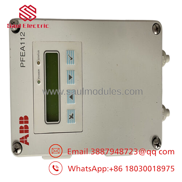
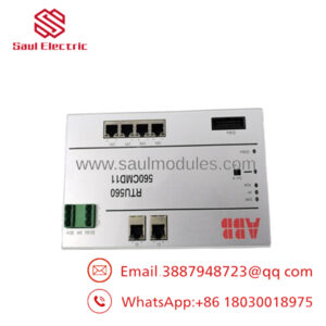
- PFEA112-65 3BSE030369R0065
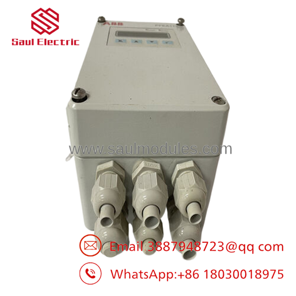
- PFEA112-65 3BSE030369R0065
Installation & Configuration Guide
Stage 1: Pre-Installation Preparation (Estimated Time: 15 minutes)
- ⚠️ Safety First: Coordinate with production operators before bringing down the line. Isolate all associated machinery, lock out and tag out (LOTO) incoming mains supply power to the tension rack, and allow 5 minutes for internal power supply capacitors to fully discharge.
- Tools Required: Grounded ESD wrist strap, PH1 and PH2 screwdrivers, a digital multimeter (such as a Fluke 115), precise wire terminal labels, and a smartphone or camera to record existing hookups.
- Data Backup: Access the configuration menu of the running unit if possible. Navigate the interactive text display and manually document the operational parameters including calibration weights, zero offsets, filter time parameters, and the PROFIBUS station network address.
Stage 2: Removing the Old Module (Estimated Time: 10 minutes)
- Loosen the four corner retaining screws on the IP65 enclosure faceplate and carefully tilt open the housing cover.
- Photograph the field terminations to preserve wire color coding and positions.
- Verify zero voltage at the incoming power terminals using your multimeter.
- Unscrew the terminal block clamp screws and slide the conductors free. Tag every single conductor immediately with its corresponding terminal number to prevent cross-wiring.
- Disconnect the PROFIBUS Sub-D connector or direct bus lines.
- Unbolt the enclosure from the machine frame or mounting plate. Inspect the mounting area for structural debris, oil residue, or heavy vibration damage.
- ⚠️ Note: Keep the pulled unit inside an anti-static bag close to the machine layout for reference until the new controller is fully commissioned.
Stage 3: Installing the New Module (Estimated Time: 15 minutes)
- Ensure your ESD wrist strap is securely connected to a verified ground point. Mount the new PFEA112-65 enclosure firmly to the mounting surface using its integrated external casting lugs.
- Set the internal hardware DIP switches on the circuit board to mirror the exact configuration of the old unit. Pay strict attention to the PROFIBUS line termination switch; it must be set to “ON” only if this controller represents the final physical node on that network trunk line.
- Land the tagged field wiring onto the screw terminals. Torque the terminal clamps down to the factory rating using a proper instrument screwdriver to prevent strip-out or high-resistance loose connections.
- Seat the PROFIBUS connector and tighten its securing side screws.
Stage 4: Power-On & Testing (Estimated Time: 20 minutes)
- Disconnect or isolate the field logic inputs/outputs and PLC system control loops to prevent accidental system activation.
- Apply input operating power (either 24 V DC or 100-240 V AC depending on your specific internal power source wiring).
- Observe the integrated LED and LCD character display. A steady green LED indicates a normal boot and successful self-diagnostics. A flashing or solid red LED points directly to an internal fault.
- Use the interface keys to enter your recorded system values: zero offset, calibration data, and the correct fieldbus address.
- Connect your programming laptop to the PLC network master and verify that the
ABB_0716.GSDprofile establishes an active data exchange without timeout faults. - Perform a physical check: exert a manual down-force directly on the tension roll and observe whether the LCD display tracking changes dynamically in the right direction. Reconnect your control outputs to restore full production capability.
- ⚠️ Troubleshooting Note: If a “Fieldbus Fault” error shows on the screen or the master PLC throws a red communication LED, double-check your network node address parameters and test the integrity of the PROFIBUS cable shields.
Frequently Asked Questions (FAQ)
Can I hot-swap this module while the web control loop is active?
Absolutely not. Pulling terminal blocks or disconnecting the load cell lines while power is running can cause severe inductive spikes that risk damaging the sensitive input amplifier circuits of the Pressductor unit or corrupting the master PLC fieldbus card. Always drop power to the tension electronics before servicing or altering any connection.
What is the exact difference between the PFEA112-65 and the PFEA112-20 models?
The difference is purely structural and environmental. The electronic boards and firmware logic are identical, but the PFEA112-20 is an open, unsealed module meant for DIN-rail attachment inside a larger, climate-controlled electrical cabinet. The version is delivered in a sealed aluminum IP65 box designed to handle wet washdowns, heavy airborne dust, and physical impacts directly out on the factory floor.
We are upgrading our network infrastructure to PROFINET. Can this module support that protocol?
The PFEA112 series relies on a physical ASIC chip designed for PROFIBUS DP networks. If your system architecture is standardizing on PROFINET or EtherNet/IP, you will need to replace this module with an ABB PFEA122 model. Alternatively, you would have to deploy an external protocol converter gateway, which adds communication latency.
Will I lose my custom load cell calibration numbers if the unit loses power?
No. The calibration values, system scaling settings, zero offsets, and configured network parameters are stored in non-volatile EEPROM memory. The module can remain completely disconnected from power indefinitely inside a dry warehouse without dropping its internal register configurations.
Why is the pricing on these new surplus units significantly lower than factory list price?
These components come out of clean storage, canceled infrastructure projects, or system configuration updates where spares were ordered but never deployed to active service. They are verified as completely unused and original OEM hardware, but because they do not bypass standard regional distributor channels, we pass the procurement cost savings directly down to your plant operations team.

 Start Chat


