





Description
Key Technical Specifications
| Parameter | Value |
| Model Designation | PM150V08 |
| Product ID | 3BSE009598R1 |
| System Compatibility | Advant Controller 150 / MasterPiece systems |
| Architecture | High-reliability dual-processor hardware topology |
| Power Requirements | Provided via the subrack backplane assembly (+5 V DC, \pm15 V DC) |
| Memory Allocation | Onboard RAM for volatile runtime variables, Flash/EPROM backup options |
| Communication Interface | Interfaces directly with backplane MasterFieldbus and CS31 bus drivers |
| Battery Backup | External connection on front/subrack for RAM retention |
| Operating Temperature | 0 to +55°C (32 to 131°F) |
| Physical Dimensions | Standard Advant subrack Eurocard form factor |
| Net Weight | 0.85 kg (1.87 lbs) |
Product Introduction
The ABB PM150V08 (3BSE009598R1) is a dual-processor CPU module acting as the central intelligence node for the legacy Advant Controller 150 (AC150) and MasterPiece systems. Engineered to process complex mathematical functions, regulatory loops, and sequential control interlocks, this board is a critical component for maintaining continuous automated execution in legacy manufacturing facilities, pulp plants, and power stations.
Running a proprietary real-time kernel, the PM150V08 coordinates high-speed communication interfaces across the local subrack backplane, linking process logic with remote CS31 I/O networks and MasterFieldbus channels. Its highly reliable component design isolates internal computation from field transients, ensuring dependable uptime when paired with clean, battery-backed auxiliary power rails.
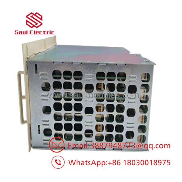
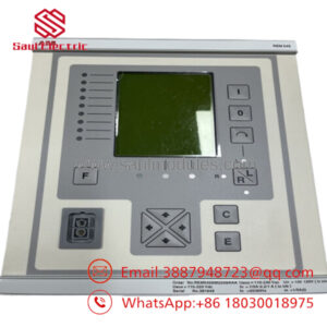
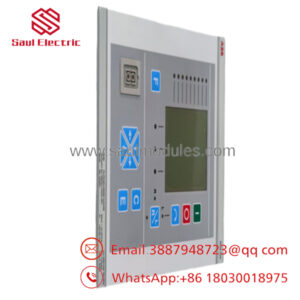
- PM150V08 3BSE009598R1
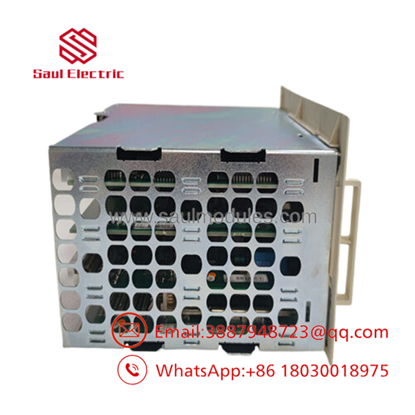
- PM150V08 3BSE009598R1
Installation & Configuration Guide
Stage 1: Pre-Installation Preparation
- Estimated Time: 20 minutes
- ⚠️ Safety First: Replacing a primary controller CPU will cause an immediate shutdown of all connected system loops. Verify that the process line is completely stopped and in a safe state. Isolate the primary power feed to the Advant subrack chassis. Lock out and tag out (LOTO) all related system power breakers.
- Tools Required: Grounded ESD wrist strap, small slot-headed screwdriver, card puller (if required by rack sub-assembly), system engineering laptop running AMPL/MasterView programming environment.
- Data Backup: CRITICAL: Before removing the old CPU module, perform a full backup upload of the application software logic (AMPL source code) and parameter configurations. The volatile RAM contents will clear when the module loses backplane power if the backup battery is drained.
Stage 2: Removing the Old Module
- Estimated Time: 5 minutes
- Steps:
- Wear your grounded ESD wrist strap and connect the clip to an unpainted part of the cabinet frame.
- Disconnect any localized external communication cables or battery connectors attached to the front faceplate interfaces.
- Loosen the upper and lower captive screws locking the module housing to the subrack.
- Carefully pull the card ejector handles outward to break the connection with the backplane socket, then slide the card smoothly out of the channel guides.
Stage 3: Installing the New Module
- Estimated Time: 10 minutes
- Steps:
- Unpack the replacement PM150V08 inside your static-safe zone.
- Inspect the rear pin arrays to verify that no pins are bent or contaminated with dust.
- Check for any internal physical jumpers or DIP switches that dictate base configuration options (e.g., node identification or memory maps) and verify they match the original module’s settings.
- Align the PCB edge with the subrack plastic guide rails and slide the card smoothly inward until it contacts the backplane connector.
- Press the module firmly into place until the card sits completely flush, then secure the top and bottom captive screws.
- Self-Checklist:
- [ ] Configuration jumpers/switches match the original CPU board
- [ ] Pin blocks aligned perfectly before applying physical pressure
- [ ] Module fully seated and locked with front panel screws
Stage 4: Power-On & Testing
- Estimated Time: 20 minutes
- Pre-Power Check: Ensure the backup battery assembly is correctly connected to the appropriate terminal to protect the configuration upon initial initialization.
- Power-On Steps:
- Restore power to the main subrack chassis supply.
- Monitor the front-panel indicator LEDs during startup:
- Green RUN/OK LED: Should light up after initialization routines pass.
- Red FAULT LED: Should flash briefly at boot and then remain off.
- Hook up your engineering tool via the dedicated communication interface slot.
- Download the stored application logic backup (AMPL project file) back into the new CPU memory space.
- Put the module into test/debug mode, verify that all backplane I/O channels read correctly, and clear any remaining diagnostic system errors before returning the system to operational mode.
- ⚠️ Troubleshooting Note: If the red FAULT LED remains lit after power-up, it typically points to a hardware configuration conflict or an uninitialized RAM space. Turn off power, pull the card, double-check that your jumper addresses match the application profile, and re-attempt the boot configuration.
Frequently Asked Questions (FAQ)
Will I lose my program when I pull the old module out of the rack?
Yes, unless you have an active backup. The runtime application logic is stored in volatile RAM. If you pull the module out of the backplane without an external battery assembly connected to the board, or if you don’t have a compiled backup copy stored on your engineering PC, the logic will be lost. Always upload and verify your backup before servicing the CPU card.
Can this module be hot-swapped while the Advant subrack is live?
No. The is the central processor card and does not support live hot-swapping in single-channel topologies. Pulling the module while the backplane is energized can cause electrical arc damage to the connector pins and will immediately crash the control loop network, dropping all outputs to their fail-safe states.
What causes a memory checksum error immediately after installation?
A checksum error occurs when the internal processor detects corrupted or missing data blocks within its non-volatile boot track or operational RAM. This is standard behavior for a blank replacement module. To resolve the error, connect your engineering terminal, perform a memory clear operation, and download a fresh, complete AMPL system configuration profile.
Why is the listed as an obsolete part, and how can I ensure long-term reliability?
The Advant 150 and MasterPiece series systems are mature architectures that have transitioned out of active manufacturing lifecycle phases. Since new parts are no longer fabricated by the factory, all available stock consists of original new surplus or certified refurbished units. To ensure high reliability, prioritize modules that undergo dynamic load testing and component-level aging evaluations before warehouse dispatch.
Do I need to update the system firmware on this card when installing it?
It depends on the system application version of your existing network. The replacement must match the firmware baseline utilized by your companion I/O systems and programming tools. Before putting the card into service, verify the firmware revision label affixed to the board’s EPROMs and ensure it aligns with your facility’s software standards.

 Start Chat


