





Description
Key Technical Specifications
| Parameter | Value |
| Model Designation | PM860K01 (Kit contains PM860 CPU, TP830 Baseplate, and TK807A Cable) |
| Product ID | 3BSE018100R1 |
| Microprocessor | 32-bit Motorola ColdFire running at 24 MHz |
| Onboard RAM | 8 MB (Non-extended, battery-backed runtime memory) |
| Power Input | 24 V DC (\pm15% via baseplate connection) |
| Current Consumption | Max 550 mA at 24 V DC (excluding external CEX-bus draw) |
| Redundancy Support | Yes, via dedicated connection to a secondary PM860 |
| Maximum I/O Capacity | Supports up to 12.5 MBd ModuleBus and CEX-bus extensions |
| Operating Temperature | +5 to +55°C (41 to 131°F) |
| Enclosure Rating | IP20 |
| Net Weight | 1.10 kg (2.43 lbs) complete kit |
Product Introduction
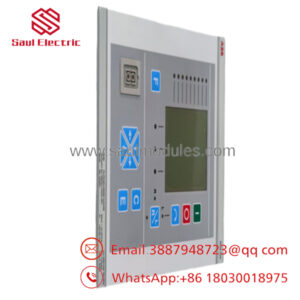
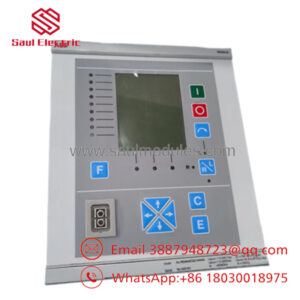
The ABB PM860K01 (3BSE018100R1) is a highly reliable central processing unit kit designed for the AC 800M control hardware platform within the System 800xA architecture. Functioning as the primary computational module for complex processing plants, this controller executes IEC 61131-3 compliant control logic, PID regulations, and sequential interlocks while directly handling local and distributed I/O systems.
The PM860 features an internal 8 MB RAM capacity optimized for mid-range automation topologies that require fast execution speeds without the footprint of higher-tier processors. The kit includes the essential TP830 baseplate framework and internal termination accessories. Built with advanced electrical isolation, the module supports full processor hardware redundancy, ensuring high-availability operation by transferring control to a hot-standby unit if a hardware or network exception occurs.
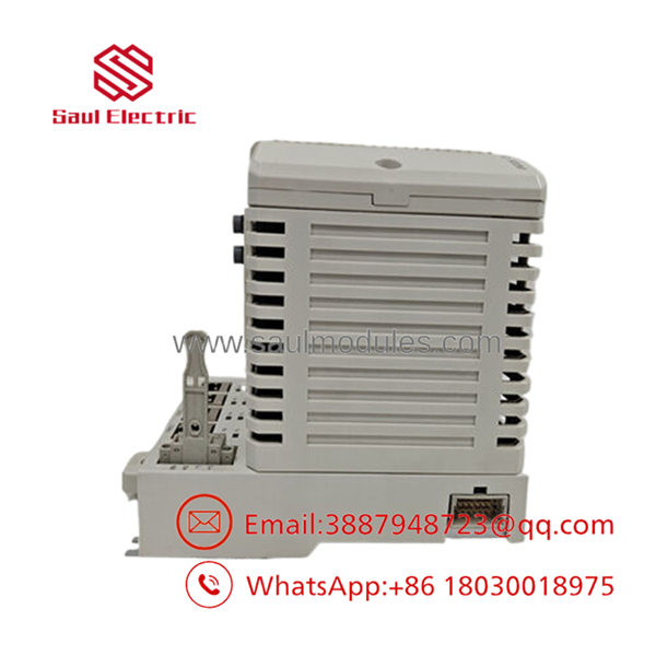
- PM860K01 3BSE018100R1
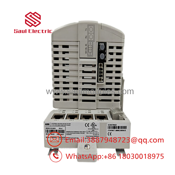
- PM860K01 3BSE018100R1
Installation & Configuration Guide
Stage 1: Pre-Installation Preparation
- Estimated Time: 15 minutes
- ⚠️ Safety First: If replacing a single, non-redundant CPU, notify the operations room immediately since pulling the module will cause a total process shutdown. Disconnect the main 24 V DC feed line to the enclosure rack. Apply standard Lockout/Tagout (LOTO) protocols to the breaker.
- Tools Required: Grounded ESD anti-static wrist strap, small flathead screwdriver, laptop with Control Builder M / Compact Control Builder software, and a clean backup battery (typically model SB821).
- Data Backup: Ensure you have the compiled project file (
.prgor source configuration) matching the exact node app version currently executing on the machine. Unpowered RAM will drop the logic if the existing board battery is low.
Stage 2: Removing the Old Module
- Estimated Time: 5 minutes
- Steps:
- Securely attach your ESD wrist strap to the unpainted enclosure ground frame.
- Disconnect any TK801V010 serial interfaces or Ethernet cables from ports CN1 and CN2 on the front faceplate.
- Loosen the upper and lower plastic captive locking clips on the front of the PM860 module casing.
- Firmly slide the CPU unit straight out from the TP830 baseplate hooks to clear the backplane connector guide array.
Stage 3: Installing the New Module
- Estimated Time: 10 minutes
- Steps:
- Position the replacement PM860 unit on your anti-static work pad.
- Open the small battery door on the unit panel and install the backup battery to initialize long-term RAM retention functionality.
- Align the upper and lower mounting hooks of the CPU module body with the receiving slots on the pre-installed TP830 baseplate.
- Press the module firmly straight back into the base structure until you hear the locking clips click into place, seating the backplane multi-pin interface flush.
- Self-Checklist:
- [ ] Internal backup battery installed and connected properly
- [ ] Rear pin headers aligned straight before final push
- [ ] Front locking clips clicked closed on the base unit
Stage 4: Power-On & Testing
- Estimated Time: 15 minutes
- Pre-Power Check: Ensure the terminating plugs are installed correctly on the right side of the ModuleBus interface assembly if no expansion units follow.
- Power-On Steps:
- Apply the 24 V DC input power to the system rack breaker.
- Watch the front-panel status lights during initialization:
- Green RUN LED: Flashes during self-test and turns solid when operating correctly.
- Red ERR LED: Should turn off post-boot (if it stays lit, a hardware fault is present).
- Amber BATT LED: Should be completely dark; if illuminated, the backup battery requires replacement or is poorly seated.
- Connect your engineering station to the CPU using a serial or Ethernet hookup.
- Match the IP address parameters, establish an online handshake, and download the verified application code onto the controller memory block.
- ⚠️ Troubleshooting Note: If you get a “Firmware Version Conflict” warning during software synchronization, navigate to the Control Builder maintenance menu and execute a firmware download to update the board’s internal flash image to match the software build level.
Frequently Asked Questions (FAQ)
Can I hot-swap a PM860 controller module while the machine is live?
Yes, but only if configured in a dual redundant layout. If the AC 800M rack contains two processors on a redundant baseplate (such as the TP830), the backup CPU runs in a hot-standby state. If the primary processor experiences an exception or is manually unclipped, the standby unit takes over control within milliseconds without dropping I/O lines. If the system is non-redundant, pulling the unit will immediately stop the control process.
What is included in the PM860K01 kit number compared to ordering a bare ?
The PM860K01 is a complete integration kit package containing the CPU processing block, the TP830 modular baseplate assembly for DIN-rail attachment, two positioning termination units, and the TK807A network connection cable. Ordering just the bare item code provides only the replacement electronic block shell without the structural interface plate or peripheral terminal items.
Why is the backup battery status so critical during plant shutdowns?
The operational logic parameters and active variable logs inside the are retained within volatile RAM blocks. If the panel experiences a full cabinet power isolation or blackout, the internal SB821 battery is the sole component maintaining the memory tracks. If the battery is drained, the CPU will lose its program allocation and require a full download upon subsequent power-up.
Does this processor module support direct PROFIBUS DP device connections?
Not directly on the front ports. The native connections on the housing are designed for Ethernet, standard serial links, and direct ModuleBus communication. To link into a PROFIBUS DP topology, you must attach a CI854A or CI854B communication interface card onto the controller’s side-mounted CEX-bus interface rail.
What is the maximum number of local I/O modules a single can support?
Through the native electrical ModuleBus connection on the baseplate assembly, a single CPU can interface with up to 12 local S800 I/O modules. If your configuration requires adding more channels, you must install an optical ModuleBus optical port link expansion module to bridge additional clusters.

 Start Chat


