





Description
Key Technical Specifications
| Parameter | Value |
| Model Designation | PM865K02 (Kit contains PM865 CPU, TP830 Baseplate, TK807A Cable) |
| Product ID | 3BSE031151R1 |
| Microprocessor | 32-bit Motorola ColdFire running at 24 MHz |
| Onboard RAM | 16 MB (Non-extended, battery-backed volatile memory) |
| Safety Integrity Level | Certified for IEC 61508 SIL1-3, ISO 13849-1 PL e, EN 954-1 Cat 4 |
| Input Power Voltage | 24 V DC (\pm15% via baseplate backplane) |
| Current Consumption | Typ 550 mA at 24 V DC (excluding external CEX-bus configurations) |
| Redundancy Support | Yes, full CPU hardware and communication link redundancy |
| Operating Temperature | +5 to +55°C (41 to 131°F) |
| Environmental Protection | Conformal coated board options available |
| Net Weight | 1.20 kg (2.65 lbs) complete kit assembly |
Product Introduction
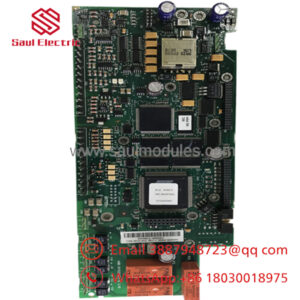
The ABB PM865K02 (3BSE031151R1) is a specialized, high-integrity central processing unit kit designed for the AC 800M hardware platform within ABB’s System 800xA architecture. Engineered specifically to meet demanding Safety Integrity Level 3 (SIL3) standards, this controller is deployed in critical applications such as Emergency Shutdown (ESD) systems, Fire and Gas (F&G) detection, and Burner Management Systems (BMS), alongside standard regulatory process control.
Housed in a rugged, modular form factor, the PM865 CPU contains 16 MB of onboard memory, offering twice the capacity of legacy safety processors to easily handle large, nested safety logic profiles. The PM865K02 kit includes the fundamental TP830 baseplate framework and standard connection cabling. When configured with a redundant partner, the PM865 utilizes an internal voting system and diagnostic routines to isolate internal faults, switching control to the standby processor within milliseconds to ensure zero process downtime on critical loops.
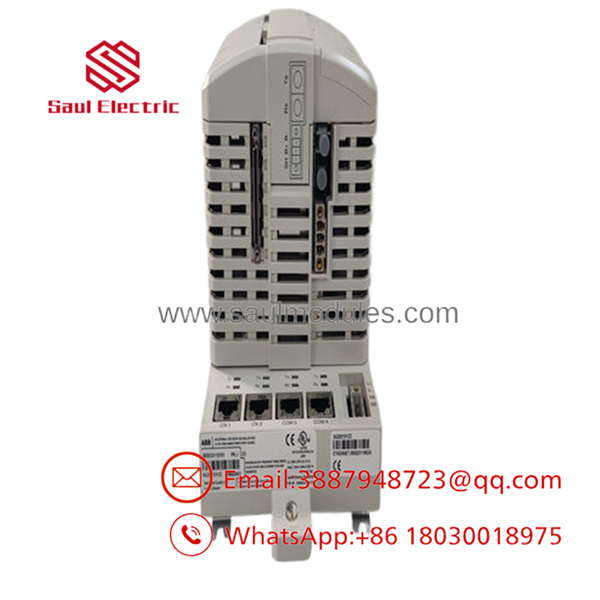
- PM865K02
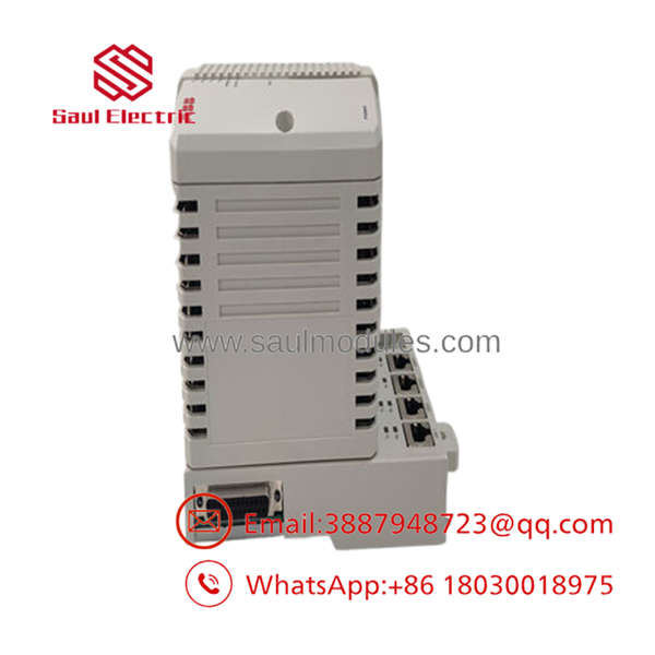
- PM865K02
Installation & Configuration Guide
Stage 1: Pre-Installation Preparation
- Estimated Time: 20 minutes
- ⚠️ Safety First: This module handles safety-critical functions (SIL1-3). Do not replace this module while the safety loop is active. If you must perform an active hot-swap on a redundant system, confirm that the redundant partner is healthy and in “Active” state. If this is a non-redundant system, ensure the entire process is safely shut down. Isolate the auxiliary 24 V DC feed breaker and apply LOTO protocols before starting work.
- Tools Required: Grounded ESD anti-static wrist strap, small flathead screwdriver, laptop with Control Builder M (or Compact Control Builder) configured with the correct safety license, and a fresh backup battery (SB821).
- Data Backup: Ensure you have an exact, compiled copy of the safety project backup (
.prgfile) matching the runtime checksum of the target controller node.
Stage 2: Removing the Old Module
- Estimated Time: 5 minutes
- Steps:
- Securely clip your ESD grounding strap to an unpainted metal surface on the cabinet frame.
- Disconnect any physical Ethernet or serial cables from ports CN1 and CN2 on the front of the PM865.
- If replacing a redundant unit, verify the module you are pulling has its status LED set to “Standby/Backup.”
- Unlatch the upper and lower plastic captive locking clips on the front housing.
- Pull the CPU module straight outward from the TP830 baseplate hooks to disengage the rear backplane connectors.
Stage 3: Installing the New Module
- Estimated Time: 15 minutes
- Steps:
- Unbox the replacement PM865 on your ESD-safe mat.
- Open the physical battery compartment and connect the fresh SB821 backup battery.
- Check any hardware jumpers on the board sides to ensure they match the addressing of the original module.
- Align the mounting hooks on the rear of the CPU unit with the receptor slots on the TP830 baseplate.
- Press the module firmly straight back until both the top and bottom latching clips click securely into place.
- Self-Checklist:
- [ ] Backup battery is connected and panel door is closed
- [ ] Rear connector pins checked for straightness before insertion
- [ ] Both front-panel clips clicked securely into the baseplate
Stage 4: Power-On & Testing
- Estimated Time: 20 minutes
- Pre-Power Check: Ensure that safety-rated I/O modules (such as the S800 High Integrity I/O) are properly terminated on the ModuleBus interface.
- Power-On Steps:
- Energize the 24 V DC system rack power breaker.
- Monitor the front-panel diagnostic LEDs:
- Green RUN LED: Flashes during self-diagnostics and remains steady upon passing.
- Red ERR LED: Must go out after the boot sequence completes.
- Amber BATT LED: Must be completely dark. If lit, the backup battery is low or disconnected.
- Establish an online connection from your engineering laptop using a serial or Ethernet hookup.
- If the controller is blank, set the IP address parameters, complete a firmware version match, and perform a full compile and download of your safety application.
- Verify that the safety checksum on your screen matches your safety system documentation.
- ⚠️ Troubleshooting Note: If the red “ERR” LED is flashing slowly, it indicates that the safety application signature has been corrupted or is not loaded. Initiate a cold-restart and re-verify the program download from Control Builder.
Frequently Asked Questions (FAQ)
Can the PM865K02 be hot-swapped while the plant is operating?
Yes, but only if configured in a redundant layout. In a dual redundant setup, the active PM865 handles all calculations, while the backup unit mirrors the state over a dedicated redundancy link. If the active unit fails, the backup assumes the primary role without disrupting process execution. If your system is non-redundant, removing the CPU will stop the controller and trip all safety outputs to their fail-safe states.
What is the purpose of the backup battery in the ?
The internal backup battery (model SB821) keeps the volatile RAM energized when cabinet control power is completely cut off or during planned maintenance blackouts. This retains the safety application program and active process configurations. If the battery is dead or missing, the controller will lose its program when powered down, requiring a full software download from your engineering laptop.
Can I mix a standard PM860 and a safety on the same redundant baseplate?
No. Redundant controller configurations must use identical CPU modules. You cannot pair a standard PM860 with a safety-certified . Doing so will prevent the modules from establishing a redundancy handshake, and the controller will throw a hardware configuration fault.
What is the difference between the and the ?
The is the bare CPU hardware block, while the is a complete physical installation kit. The kit includes the CPU module, the TP830 baseplate for DIN-rail mounting, two lateral positioning termination units, and the TK807A network connection cable. Purchasing the kit ensures you have all the necessary components for a fresh installation or full slot replacement.
How do I clear a “Safety Firmware Mismatch” error?
If your engineering laptop returns a firmware conflict error during connection, the operating system loaded on the flash memory does not match the version of your Control Builder project. To resolve this, switch the controller to “Stop” or “Service” mode, select the firmware upgrade tool in your engineering suite, and flash the CPU’s internal ROM to match your project’s version.

 Start Chat


