





Description
Key Technical Specifications
| Parameter | Specification / Value |
| Model Number | PPC322BE1 / PPC322 BE |
| Part Number (ID) | HIEE300900R0001 |
| Processor Type | PSR-2 32-bit RISC |
| Processor Clock Speed | 100 MHz |
| Onboard Memory | 128 MB RAM |
| Supported Protocols | PROFIBUS DP, Modbus RTU, Modbus TCP |
| Physical Interfaces | 2x RS-232, 1x Ethernet, 1x RS-485 |
| Input Supply Voltage | 24 V DC (nominal) |
| Operating Temperature | -20 °C to +60 °C |
| Inbound Isolation | 3,000 V channel-to-channel |
| Form Factor / Protection | Compact, IP20 rated |
| Net Weight | 1.15 kg (2.53 lbs) |
| Dimensions (W x H x D) | 29 mm x 29 mm x 29 mm (Sub-module assembly footprint) |
Product Introduction
The ABB PPC322BE1 (HIEE300900R0001) is a high-reliability PSR-2 processor and fieldbus communication module designed for the ABB Safeguard and associated process control platforms. Engineered to handle high-speed data processing and demanding communication handshakes simultaneously, this unit operates as a central control and coordination node in industrial automation environments.
Unlike standard controllers, the PPC322BE1 integrates a dedicated 32-bit RISC processor with robust galvanic isolation rated up to 3,000 V. This specialized architecture ensures steady operation in high-noise, high-voltage industrial applications such as power generation, marine navigation systems, and petrochemical processing. By bridging physical I/O to multi-protocol field networks like PROFIBUS DP and Modbus, it prevents data bottlenecks and maintains deterministic control loop timing.
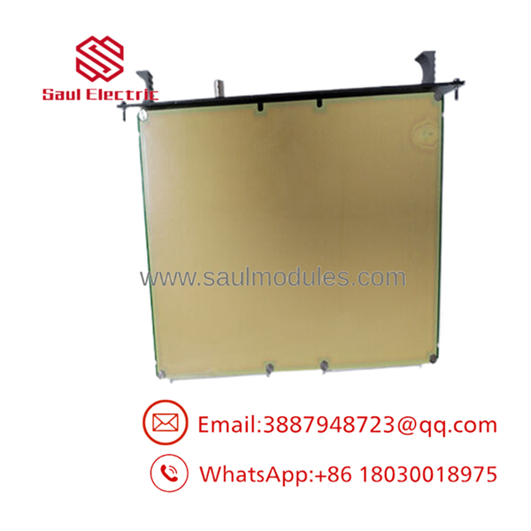
- PPC322BE1
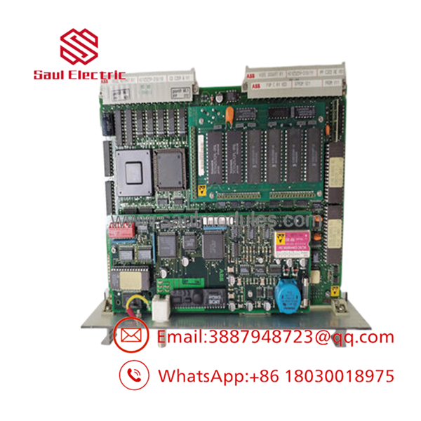
- PPC322BE1
Installation & Configuration Guide
This technical guide outlines the procedures for replacing a failed or legacy controller with a new PPC322BE1 module.
Stage 1: Pre-Installation Preparation (Est. Time: 10 minutes)
- ⚠️ Safety First: Prior to carrying out any work, notify the operations control room of the planned downtime. Ensure the system is brought to a safe, controlled state. Isolate the main 24 V DC power supply feed to the rack. Lock out and tag out (LOTO) all power disconnects. Wait at least 5 minutes to allow internal bus capacitors to discharge fully.
- Tools Required: Grounded ESD wrist strap, small flat-head screwdriver, digital multimeter, wire labels, and a smartphone or camera.
- Data Backup: Connect your programming terminal to the existing processor. Export and back up the running logic, communication configuration parameters, and network IP nodes.
Stage 2: Removing the Old Module (Est. Time: 5 minutes)
- Attach your grounded ESD wrist strap to the clean metal chassis of the rack.
- Remove any front protective bezels or module covers.
- Use a digital multimeter to verify that the 24 V DC terminals on the terminal block are completely de-energized.
- Label all connected communication cables (Ethernet, Serial, and Fieldbus) to avoid post-replacement configuration errors. Carefully disconnect them.
- Release the rack locking tabs or mounting screws. Slide the module straight out of the rack guide rails. Avoid rocking the module side-to-side to protect the backplane pins from bending or shearing.
- Inspect the vacant backplane slot for dust, debris, or compromised socket pins. Clean with low-pressure compressed air if necessary.
Stage 3: Installing the New Module (Est. Time: 10 minutes)
- Remove the new from its ESD-protective packaging.
- Configuration Clone (Crucial): Examine the physical hardware of the old module. Replicate any physical jumper settings, DIP switches, and terminating resistor positions exactly onto the new module.
- Slide the new module smoothly into the guide rails of the rack until you hear it click into place, indicating complete seating in the backplane.
- Secure the module housing using the integrated rack locking tabs.
- Reconnect the communication and serial cables to their designated ports according to the labels applied in Stage 2.
Self-Checklist:
- [ ] DIP switches match old configuration
- [ ] Fieldbus connectors seated and locked
- [ ] Module mechanically locked to the rack slot
- [ ] Grounding strap worn during the entire swap
Stage 4: Power-On & Testing (Est. Time: 5 minutes)
- Before restoring system power, perform a quick continuity test across the 24 V DC power terminals using a multimeter to ensure there are no short circuits.
- Restore power to the rack.
- Observe the LED startup sequence:
- Power / Run LED: Solid Green indicates normal operating status.
- Error / Fault LED: If this flashes or turns solid Red, immediately check for a firmware revision mismatch or communication conflict.
- Connect your engineering laptop via the Ethernet or serial service port. Check that the module matches the network configuration and firmware version of your system database.
- Initiate a dry run to verify communication and fieldbus handshake loops before placing the loop back into automatic/running status.
Frequently Asked Questions (FAQ)
Can the ABB module be hot-swapped while the rack is powered?
No. This module does not support hot-swapping under power. Attempting to extract or insert the while the rack is energized can cause an electrical arc across the backplane connections, which risks frying the internal 32-bit RISC processor or corrupting adjacent modules. Always isolate the 24 V DC supply before replacing this unit.
If my original module has a different firmware version, will the new one work out of the box?
It depends on how far apart the firmware versions are. If your existing master controller or software expects an older firmware version (e.g., V2.x) and this replacement is loaded with V3.x, the system may flag a “Communication Mismatch” and refuse to handshake. It is highly recommended to compare the firmware version on the faceplate sticker of your original module with the replacement unit, and flash/downgrade the replacement module’s firmware to match if necessary.
Will I lose my running program or network configuration when I pull the old processor?
Yes, the application logic and system configuration are volatile within the processor module’s active RAM. To prevent losing your configuration, you must upload and save a backup of the system database and logic files using your system configuration software before removing the old module.
What is the difference between the and older PPC322BE01 models?
The is a hardware revision of the older PPC322BE01. While they share similar fundamental features (the PSR-2 processing architecture and support for Modbus/PROFIBUS), the features upgraded electronic components, improved thermal dissipation, and revised internal circuitry. It acts as a backward-compatible replacement in almost all configurations, though you should verify that your specific rack backplane slot and firmware revision support the newer hardware stepping.
What causes the Error (ERR) LED to light up red immediately after installation?
If the Red ERR LED lights up immediately after booting, it typically points to one of three common issues:
- DIP Switch Mismatch: The physical network node or address switches on the side of the module do not match the software project.
- Firmware Incompatibility: The firmware loaded on the module is incompatible with the rest of the rack assembly.
- Backplane Seating Issue: The module is not fully pushed into the rack, causing a bad connection on the backplane interface pins.



 Start Chat


