



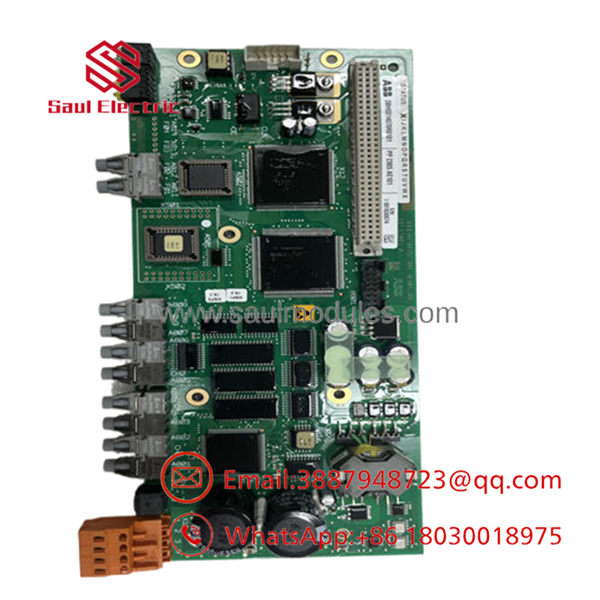
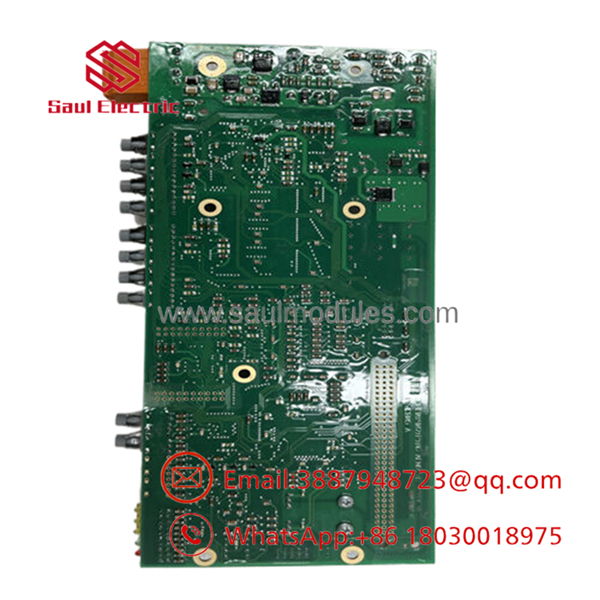


Description
Key Technical Specifications
| Parameter | Specification / Value |
| Model Number | PPC905AE101 |
| Part Number (ID) | 3BHE014070R0101 / 3BHE014071P201 |
| Board Identifier | CCB-2 COMPLETE (Converter Control Board) |
| Compatible Systems | ABB ACS6000 medium voltage drives, PCS600 excitation/converter systems |
| Processor Clock & Logic | Embedded High-Speed Microprocessor |
| Input Supply Voltage | 24 V DC nominal (18–32 V DC operational range) |
| I/O Integration | 16x Digital Inputs, 16x Digital Outputs (2 A per channel capacity) |
| Serial Interfaces | 2x RS-232 / RS-485 configurable ports |
| Network Interfaces | 2x RJ45 Fast Ethernet ports |
| Optical Interfaces | Direct fiber-optic links for converter phase control integration |
| Operating Temperature | -20 °C to +70 °C |
| Module Dimensions | 250 mm x 100 mm footprint |
| Net Weight | 0.25 kg (board only) / approx. 0.60 kg with metal carrier shield |
Product Introduction
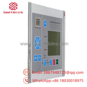
The ABB PPC905AE101 (3BHE014070R0101) is a high-performance Converter Control Board (CCB-2) serving as the primary processing and regulation core in ABB ACS6000 medium voltage AC drive systems and PCS600 power converters. This card calculates rapid motor control algorithms, managing critical parameters like torque, direct self-control (DSC) loops, and system-wide diagnostic monitoring.
Operating at the heart of high-power industrial motor drives, the PPC905AE101 coordinates real-time speed regulation by translating high-level commands from a master PLC or DCS into immediate switching cycles for downstream power semiconductors. It features native, galvanic isolation interfaces and fiber-optic communication channels to ensure noise-free data transport in electrically hostile environments typical of rolling mills, heavy marine propulsion, and large water pumping stations.
Standard Operating Procedure (SOP): Quality Control & Testing
To eliminate risk when deploying critical drive components, we subject every inventory unit to a comprehensive five-stage validation protocol before it leaves our facility.
1. Inbound Inspection & Traceability
- Verification: Serial number verification against original ABB factory packing lists and customs manifests to guarantee authentic origin.
- Structural Check: Visual microscopic inspection for cold solder joints, PCB hairline fractures, scratched copper traces, or signs of conformal coating degradation.
- Completeness: Verification of the 3BHE014071P201 base board and all factory-installed sub-component daughterboards.
2. Live Functional Testing
- Simulation Testbed: We seat the PPC905AE101 board in a dedicated testing chassis powered by a stabilized linear 24 V DC power supply.
- Boot-Up Sequence Monitoring: The unit runs through its complete internal POST (Power-On Self-Test) routine while we monitor status LEDs to confirm nominal system boot.
- Fiber-Optic Loopback: Fiber-optic ports are fitted with physical loopback cables to verify transmitter and receiver signal integrity under load.
- Communication Diagnostics: Ping and communication handshakes are run across both RJ45 Ethernet ports and serial channels to verify zero packet drop.
3. Electrical Parametric Verification
- Ground Isolation: Using a calibrated Fluke insulation tester, we perform an insulation resistance check (>10 MΩ at 500 V DC) between the input ground rails and active control logic.
- Thermal Validation: The board undergoes a continuous 12-hour thermal burn-in run under load inside an environmental test chamber to guarantee stable frequency regulation across its operational envelope.
- Test Documentation: A serialized test report detailing current draws, boot times, and port diagnostics is archived and shipped alongside the hardware.
Technical Pitfall & Survival Guide
Replacing a high-voltage drive control card requires precise execution. Avoid these five common installation traps to prevent commissioning delays:
- ❗ Firmware Alignment Check:
- The Trap: Swapping the PPC905AE101 board without verifying the loaded application software version. If the new card runs a different application firmware version than the remaining active phase units in an ACS6000 lineup, the system will trigger a severe synchronization fault.
- The Fix: Prior to removal, read out the firmware version of the old card via your engineering tool. Request our technical team to pre-flash the replacement board to your exact required version before shipping.
- ❗ Optoelectronic Fiber-Optic Care:
- The Trap: Contaminating the delicate fiber-optic ports during handling. A single speck of grease or dust inside the optical receiver will attenuate the light signal, leading to intermittent “Phase Loss” or “Gate Driver Communication” trip events.
- The Fix: Keep the protective plastic caps on the optical ports until the exact second you plug in the fiber runs. Clean the fiber tips with specialized lint-free optical wipes.
- ❗ Shielding and Grounding Failures:
- The Trap: Neglecting the grounding connection of the metal backplane carrier. High-frequency electrical noise from the inverter’s IGBT switching will easily couple into the control circuit, resulting in phantom trips and CPU resets.
- The Fix: Ensure the mounting screws securing the board bracket to the cabinet frame are tightened to the specified torque. This maintains a low-impedance path to chassis ground.
- ❗ Improper External 24 V DC Regulation:
- The Trap: Powering the control board with a low-grade or shared industrial power supply. Voltage dips caused by nearby contactors or solenoids switching can force the PPC905AE101 to crash mid-operation.
- The Fix: Always use a dedicated, isolated Class 2 regulated 24 V DC power source with an integrated UPS or capacitor buffer module.
- ❗ Inadvertent Electrostatic Discharge (ESD):
- The Trap: Picking up the board bare-handed. The microprocessors and optical transceivers on this board are extremely static-sensitive and can be damaged permanently without immediate signs of failure.
- The Fix: Wear a grounded ESD wrist strap connected to a verified ground point before removing the board from its silver static-shielding bag.
Frequently Asked Questions (FAQ)
Can this control board be hot-swapped while the ACS6000 drive is operating?
Absolutely not. Removing or inserting the while the drive control cabinet is energized will cause high-voltage transients on the backplane, destroying the digital processing ICs and presenting a severe arc-flash safety hazard to the technician. The entire drive cabinet must be isolated, locked out, and verified to have zero residual voltage in the DC link capacitors before replacing the board.
What is the relationship between the board model and the part number 3BHE014070R0101?
is the official functional model designation used by ABB to define this hardware configuration (CCB-2 Complete). The number 3BHE014070R0101 is the unique OEM spare part number used by ABB’s logistics, ordering, and service databases. They refer to the exact same physical and functional assembly.
Does this board require parameter programming upon installation?
Yes. The is a processing unit. Once physically installed, you must load the specific drive application parameter set, motor mathematical models, and network communication configurations using your ABB DriveWindow or System 800xA engineering interface. A blank card will not drive a motor.
Why is there a price difference between your surplus and factory-new direct orders?
We source our inventory from project cancellations, system upgrades, and factory-overstock reserves. This allows us to offer genuine, unused OEM components at a substantial discount compared to standard factory lead-time pricing, while still backing the hardware with our complete 12-month warranty.
How are the 16 digital inputs on the board protected against field electrical surges?
The digital inputs are opto-isolated to withstand common-mode voltage spikes up to 120 V DC. This isolation barrier safeguards the delicate internal microprocessor from external field faults, such as shorted sensor cables or ground loops.

 Start Chat


