





Description
Key Technical Specifications
| Parameter | Value |
| Main Functionality | Measurement, Monitoring, Control, Protection, Communication, Self-Diagnostics |
| System Architecture | Split design: Base Unit (Processing & I/O) and independent Human Machine Interface (HMI) |
| Analog Inputs | Up to 8 channels, accommodating conventional instrument transformers (CT/VT) or non-inductive linear sensors (Rogowski coils/voltage dividers) |
| Sampling Rate (Fault Recorder) | 1.2 kHz across analog channels |
| Binary I/O Capacity | Modular configuration with dedicated watchdog contacts per module |
| Communication Protocols | IEC 61850, Modbus RTU, Profibus DP, LonWorks, IEC 60870-5-103 |
| Configuration Software | ABB Operating Tool / FUPLA (Function Block Diagram Programming Language) |
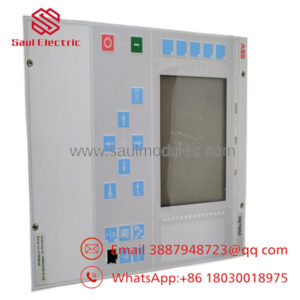
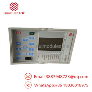
| Front HMI Display | Multi-line LCD text display with a dedicated programmable single-line diagram sector |
| Protection Profile Capability | Overcurrent (50/51), Earth Fault (50N/51N/67N), Distance Protection (21), Thermal Overload (49), Motor/Transformer Differential (87) |
| Operating Temperature Range | −5 to +55 °C (+23 to +131 °F) |
| Ingress Protection (HMI Front) | IP54 standard (IP65 available with specialized enclosure gasket kits) |
Product Introduction
The ABB REF542plus is a compact, digital switchbay protection and control terminal engineered for medium-voltage electrical distribution networks. Representing a classic baseline in digital substation technology, the device integrates multi-parameter measurement, advanced protection algorithms, direct breaker control, and automated self-diagnostics into a single split-chassis package. It functions as the central intelligence hub within air-insulated switchgear (AIS) and gas-insulated switchgear (GIS) environments, safeguarding downstream feeders, transformers, and heavy motors.
The architecture of the REF542plus separates the core signal processing hardware from the human interface. The rugged base unit installs securely inside the low-voltage control compartment, while the separate, multilingual HMI panel mounts directly onto the cubicle door. This layout eliminates high-voltage routing risks near the door hinge. Furthermore, the unit features flexible analog processing front-ends that interface with standard 1 A / 5 A instrument transformers or modern, high-linearity non-conventional sensors, offering system integrators a reliable path for substation modernization projects.
Comprehensive SOP Quality Control & Testing
To safeguard medium-voltage substation stability and eliminate the risk of latent module failure, every legacy or surplus REF542plus terminal passes through a strict engineering test protocol before field dispatch.
1. Inbound Inspection & Traceability
- Hardware Suffix Audit: We check the hardware revision matrices and software license labels on the chassis against original factory shipping logs to identify the exact internal card configuration.
- Chassis & Bezel Verification: Technicians inspect the unit for stress fractures, tarnished terminal block pins, damaged fiber-optic ports, or un-seated sub-cards.
- Component Decontamination: Dust or atmospheric filming is cleared from the base unit using high-purity electronic cleaner.
2. Live Functional Testing
- Test Environment: The terminal is installed into a dedicated secondary injection test rack utilizing an Omicron protection test set.
- Power-On Self-Test (POST): We energize the auxiliary power input and observe the initial boot sequence, verifying the internal watchdog relay contacts state changes appropriately and that the HMI initializes without graphic anomalies.
- Analog Vector Injection: Balanced three-phase currents and voltages are injected into the analog input board. We compare the values displayed on the HMI display against the injection source parameters to confirm scaling accuracy.
- FUPLA Logic & Binary I/O Check: Using the REF542plus Configuration Tool, we cycle every programmable binary input and output, mapping physical terminal responses back to internal logic gates.
- Fault Recorder & Memory Stability: We simulate a transient trip event to verify the fault recorder writes its 1.2 kHz data capture accurately to non-volatile memory, then extract the COMTRADE file via the HMI service port.
3. Electrical Parameter Testing
- Insulation Barriers: A 500 V DC insulation test is applied between current transformer (CT) input blocks and the chassis ground point via a Fluke 1507 megohmmeter to ensure isolation barriers measure >10 MΩ.
- Ground Track Continuity: We verify the low-resistance bonding path from the chassis ground screw to the rear sub-assembly plates to confirm values reside below 0.1 Ω.
4. Firmware & Configuration Verification
- License and Patch Review: The baseline software version (e.g., Release 2.0 or Release 3.0 profiles) is verified. License configurations (Basic, Low, or High protection bands) are documented to ensure matches with your site requirements.
- HMI Communication Link: The specialized serial patch link between the base unit and the door-mounted HMI is tested continuously to ensure communication stability.
5. Final QC & ESD Packaging
- Certification: The testing engineer registers the serial number and affixes a dated calibration pass seal over the card joints.
- Static Shielding: The base unit and its companion HMI are separated, protected with scratch-resistant film, and placed into dedicated anti-static ESD bags.
- Heavy-Duty Cushioning: The items are nested inside custom-molded high-density foam within a double-wall corrugated box to absorb shipping vibration.
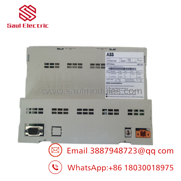
- REF542plus
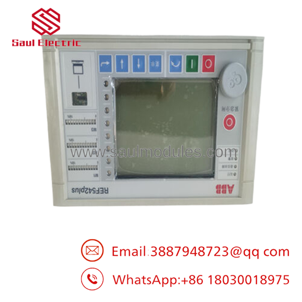
- REF542plus
Technical Pitfall & Replacement Survival Guide
Deploying or replacing a REF542plus terminal in live medium-voltage switchgear bays requires close attention to system configuration details. Avoid these five common installation oversights to prevent unintended trips and component damage.
1. Software Configuration License Constraints
- ❗ The Risk: The REF542plus uses a firmware licensing system (Basic Low, Basic, High, etc.) that restricts available functional blocks. If your replacement unit lacks the high-tier license required for specific protection curves used in your original configuration (such as distance protection 21 or differential protection 87), importing the old configuration file will cause a compile error, rendering the relay unable to protect the bay.
- 🛠| Mitigation: Extract the full type designation code and internal software version from your active relay before ordering a replacement. Ensure the replacement model number matches the license criteria required by your plant’s engineering software.
2. FUPLA Configuration Tool Modification Hazards
- ❗ The Risk: Making logic modifications inside the Function Plan (FUPLA) environment without full familiarity can disrupt internal task processing priorities. If protection algorithms and interlocking logic are assigned to incorrect cycle loops, the relay’s trip execution times can slow down significantly, leading to delayed breaker clearing during a high-current fault.
- 🛠| Mitigation: Do not modify working FUPLA applications during an emergency replacement. Upload the exact compiled configuration file from the old relay into the replacement terminal. If you must adjust settings, always run a full simulation check prior to recommissioning.
3. Open CT Secondary Circuit Hazards
- ❗ The Risk: Disconnecting the analog input lines from the back of the REF542plus base unit while the primary medium-voltage line is energized will open-circuit the current transformers (CTs). This generates extreme voltage arcs across the terminal block, destroying the internal analog card and exposing personnel to hazardous high voltages.
- 🛠| Mitigation: Always verify that the primary feeder circuit breaker is locked out and tagged out before touching the secondary terminal blocks. Alternatively, secure the secondary CT wires using external, dedicated shorting terminal blocks before disconnecting the relay lines.
4. Fiber-Optic HMI Communication Cable Attenuation
- ❗ The Risk: The link between the base unit and the remote HMI panel often utilizes optical fibers or shielded copper patch leads. Bending these cables beyond their specified minimum radius during panel door installation introduces high optical attenuation or data drops, causing intermittent “HMI Communication Timeout” faults.
- 🛠| Mitigation: Route the HMI connection cable along the swing frame axis with a smooth loop. Maintain a bending radius of at least 50 mm for optical fibers, and secure the line using loose-fit cable ties to prevent pinching when the cubicle door opens and closes.
5. Watchdog Status Integration Errors
- ❗ The Risk: Every input/output card in the REF542plus features an independent, hardware-driven internal watchdog contact. If these contacts are omitted from your master annunciator panel or SCADA safety loops, an internal component failure could disable the relay silently, leaving the substation unprotected against subsequent overcurrent faults.
- 🛠| Mitigation: Wire the dedicated normally closed (NC) watchdog fault contact from the terminal block directly back into your station alarm system. Test the loop by momentarily dropping auxiliary power to the relay to verify that a “Relay Fault” signal generates instantly on your SCADA screen.
Frequently Asked Questions (FAQ)
Can the REF542plus be directly integrated into an IEC 61850 substation network?
Yes, but it depends on the release version. Early legacy models of the REF542 device do not support modern network structures. However, the later REF542plus Release 3.0 variant includes an optional ethernet communication module interface configured specifically to support IEC 61850 station bus protocols. You must check that your specific base unit has the correct communications card slot filled and that your firmware license enables the IEC 61850 function blocks.
What is the purpose of the split architecture between the base unit and the HMI?
The split design is utilized primarily for safety and thermal isolation inside medium-voltage cubicles. The base unit handles high-voltage inputs from current and voltage transformers and installs securely inside the low-voltage control box. The separate HMI operates on an isolated low-voltage power circuit and mounts on the door face. This configuration isolates operators from the analog measurement lines and ensures that panel door movement does not stress critical measurement wiring.
Can I upgrade my analog inputs from traditional CTs to Rogowski sensors?
Yes, the REF542plus hardware supports this capability. The internal analog input board can be specified with electronic components designed to handle low-voltage inputs from non-conventional current sensors (Rogowski coils) and voltage dividers. However, you cannot wire low-power sensors into a base unit that was originally configured for standard 1 A / 5 A current transformers. The analog input card layout must match your choice of sensor technology.
What occurs if the internal real-time clock battery on the base unit fails?
If the internal memory backup battery fails, the REF542plus will continue to execute its core protection logic and handle binary input/output configurations normally when powered. However, the system’s real-time clock will reset to a default baseline value whenever auxiliary power is interrupted. This will cause subsequent entries in the internal fault recorder and event log to display incorrect time-stamps, complicating post-fault analysis.
Since ABB declared this series legacy, how do you provide functional stock?
Our inventory consists of verified new surplus units sourced from cancelled capital expansion projects, utility overstock reserves, and specialized facility updates. Because many industrial sites continue to rely on the REF542plus across their existing infrastructure, we maintain these legacy assets to help engineers replace broken units quickly without incurring the high costs and downtime of a full substation modernization.

 Start Chat


