





Description
Hardware Suffix & Configuration Breakdown
The specific hardware matrix, integrated communication cards, and functional software licenses for the type code HBFGDAAHNDCCBNA11G are detailed below:
| Code Segment | Position Meaning | Specific Hardware / Software Selection |
| HB | Product Series | REF615 Feeder Protection Relay |
| G | Standard Configuration | Configuration G: Directional overcurrent and earth-fault protection, voltage, frequency, power, and energy measurements, synchrocheck, and breaker control |
| F | Analog Inputs | 4 Current Transformers (CT) + 5 Voltage Transformers (VT) configuration |
| DA | Binary Inputs / Outputs | High-density binary input/output expansion board allocation |
| A | Protocol / Communication Slot | Standard communication card interface slot |
| H | Engineering Language | English and designated regional secondary language pack |
| N | Power Supply | 48–240 V AC / 24–240 V DC nominal input range |
| D | Communication Interface | Dual 100Base-TX RJ45 Ethernet communication card (Supports redundancy loops) |
| C | Communication Protocol | IEC 61850, Modbus, DNP3, IEC 60870-5-103 |
| 6 | Front Panel / HMI | Large graphic LCD screen with customizable single-line diagram interface |
| B | Regional Settings | IEC default characteristics, 50/60 Hz system frequency allocation |
| N | Application Options | None (Standard functionality package) |
| A | Conformal Coating | Standard lacquer protection coating on internal printed circuit board assemblies |
| 11G | Product Version | Generation / Revision baseline markers (REF615 v5.0/v6.0 family line) |
Key Technical Specifications
| Parameter | Value |
| Nominal Power Supply (U_{aux}) | 48–240 V AC (50/60 Hz) / 24–240 V DC |
| Power Consumption | ~13 W (typical baseline running draw) |
| Analog CT Channels | 3 Phase Currents + 1 Sensitive/Residual Earth Current (I_0) |
| Analog VT Channels | 3 Phase Voltages + 1 Residual/Open-Delta Voltage (U_0) + 1 Bus/Line Synchronization Voltage (U_{bus}) |
| Rated Frequency (f_n) | 50 Hz or 60 Hz software selectable |
| Rated Current (I_n) | 1 A / 5 A software programmable via internal current transformer tap scales |
| Rated Voltage (U_n) | 100 V, 110 V, 115 V, or 120 V AC phase-to-phase allocation |
| Front Service Port | 1 x RJ45 (Dedicated for local PCM600 tool engineering interface) |
| Rear Communication Ports | 2 x RJ45 Ethernet ports for redundant station bus architectures (STP/RSTP/PRP/HSR) |
| Enclosure Protection Class | IP54 Front panel (when flush-mounted using standard gasket), IP20 Rear housing |
| Enclosure Width | 177 mm (4U rack height frame) |
| Operating Temperature | −25 to +55 °C (−13 to +131 °F) continuous operation |
Product Introduction
The ABB REF615E_1G (specifically type code HBFGDAAHNDCCBNA11G) is a high-capability, numerical feeder protection and control relay belonging to the specialized ABB Relion 615 family. Configured under Standard Configuration G, this unit provides an extensive suite of directional overcurrent, earth-fault, and multi-stage voltage/frequency protection algorithms. It is primarily deployed in utility substations, complex industrial distribution networks, and grid integration systems that demand integrated power quality logging, synchrocheck-driven manual/automatic breaker closing, and network automation.
This specific variant features an advanced 4 CT + 5 VT hardware allocation. The fifth voltage transformer channel allows the relay to independently measure a line or busbar voltage segment outside the primary local three-phase set, enabling native hardware evaluation for synchrocheck (25) operations prior to re-energizing a segmented tie breaker. Outfitted with dual rear RJ45 Ethernet ports, this terminal supports advanced Ethernet network redundancy protocols (such as PRP or RSTP) alongside native IEC 61850 capabilities, enabling high-reliability, zero-packet-loss communication across critical plant architectures.
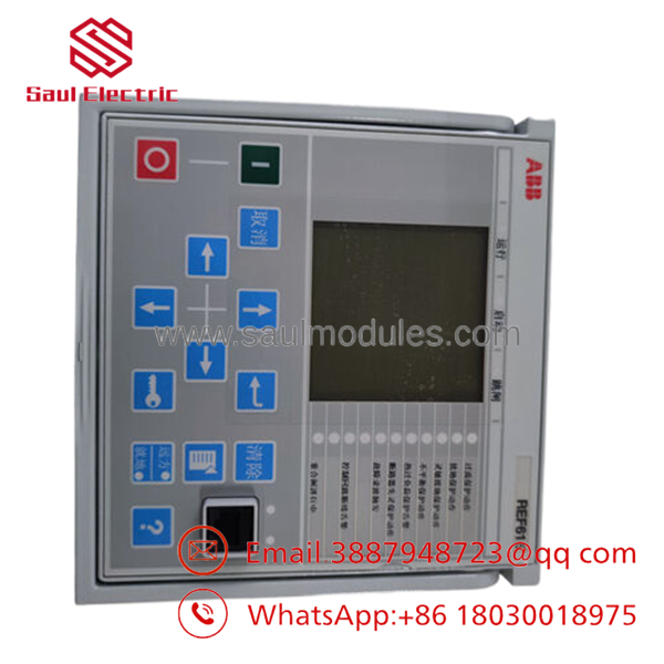
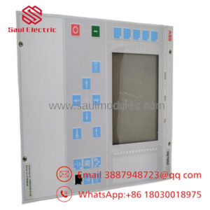
- REF615E_1G HBFGDAAHNDCCBNA11G
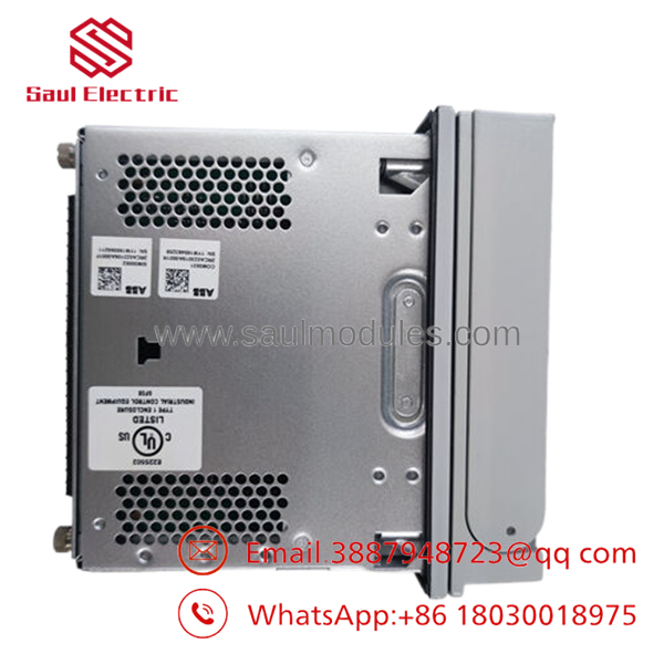
- REF615E_1G HBFGDAAHNDCCBNA11G
Comprehensive SOP Quality Control & Testing
To eliminate field commissioning complications and verify hardware baseline conformity, this REF615 terminal undergoes a standardized multi-step diagnostic review before shipping.
1. Inbound Inspection & Traceability
- Type Code Decode: The literal text string HBFGDAAHNDCCBNA11G is matched against the casing laser print and the embedded microcontroller electronic serial ID to ensure it has not been modified.
- Chassis Physical Integrity: We inspect the draw-out unit mechanism, securing levers, and connection fingers for structural warping or contact surface wear.
- Rear Connector Audit: The spring-loaded CT shorting bars inside the terminal housing are inspected to ensure they function safely during module removal.
2. Live Functional Testing
- Test Environment: The relay is inserted into a standardized configuration rack and linked via an Ethernet switch to an engineering workstation running ABB PCM600 Configuration Software.
- Boot Profile Verification: The device is energized using an auxiliary DC source. Technicians verify that the self-supervision watchdog system initializes cleanly without throwing an internal fault error.
- Analog Injection Scaling Calibration: Using a computerized multi-phase relay test set, we inject low-level current and voltage signals into the rear terminals, monitoring the PCM600 online tool to confirm measurement accuracy across all 4 CT and 5 VT channels (with specific verification on the 5th U_{bus} synchrocheck channel).
- GOOSE and Redundancy Port Traffic Validation: Both rear RJ45 ports are loaded into a packet sniffer tool to verify proper network negotiation, dual-port redundancy packet replication, and data transmission across IEC 61850 parameters.
- Report Logging: Measurement logs, serial indices, and communication logs are saved to an official QC test certificate.
3. Electrical Parameter Testing
- Dielectric Isolation Verification: A 500 V DC isolation test is conducted between independent binary circuits, analog input groups, and the main chassis grounding pad using a Fluke 1507 megohmmeter to ensure isolation barriers measure >10 MΩ.
- Chassis Ground Resistance: Ground track paths are audited from the main backplane ground lug to the outer door casing to verify values are under 0.1 Ω.
4. Firmware & Configuration Verification
- Software Version Alignments: The baseline firmware generation (e.g., Version 5.0 or 6.0 profiles) is documented. Standard configuration parameters for Configuration G are reloaded to factory baselines unless custom customer configuration files are provided.
- Internal Battery Assessment: The internal capacitor/battery health metric is checked to guarantee time-stamped disturbance records remain preserved through localized system power failures.
5. Final QC & ESD Packaging
- Approval Marking: The checking technician applies a unique tracking label over the frame seam.
- ESD and Physical Armor Packing: The relay assembly is placed inside an anti-static ESD bag, surrounded by thick polyethylene foam end-caps, and packed into a double-wall corrugated box engineered for global transport.
Technical Pitfall & Replacement Survival Guide
Replacing a numerical protection relay on a live medium-voltage switchgear bay introduces several operational challenges. Review these five common field issues to prevent component damage or accidental breaker operations.
1. Drawing Out the Internal Relay Core Under Load
- ❗ The Risk: The Relion 615 series features a convenient draw-out design that allows the internal electronics chassis to be extracted while leaving the outer casing and wiring intact. However, if the current transformer (CT) secondary wiring circuit fails to short-circuit correctly inside the case when the unit is pulled, it will cause an open CT loop. This generates dangerous high-voltage spikes, which can destroy the transformer insulation and create a safety hazard.
- 🛠| Mitigation: Never pull the relay core out while the primary circuit breaker is closed and current is flowing through the feeder. Isolate the primary feeder or manually short-circuit the external CT test block prior to extracting the internal module.
2. Standard Configuration Application Matching Error
- ❗ The Risk: Ordering a generic REF615 without matching the exact configuration letter code (e.g., swapping a Configuration G unit with a Configuration F unit) alters the physical input/output card layout. A Configuration F unit lacks the 5th VT analog board channel required to route the independent line/bus voltage vector (U_{bus}) needed for the synchrocheck loops used in Configuration G. A configuration file mismatch will prevent system import and leave the breaker interlocking scheme non-functional.
- 🛠| Mitigation: Before mounting the replacement, compare the type code string letter by letter. Ensure the third position reads G, confirming that the internal multi-channel analog cards match your existing layout exactly.
3. Missing Local PCM600 Parameter File Backups
- ❗ The Risk: A new surplus relay arrives with generic factory setting baselines. Simply plugging the unit into the rack without uploading your specific protection parameters (such as trip curves, pick-up currents, synchrocheck phase-angle windows, and time-multiplier delays) will cause the relay to trip using default settings, resulting in nuisance trips or delayed fault clearing.
- 🛠| Mitigation: Connect your laptop to the front RJ45 service port of the old relay using the PCM600 tool before removing it. Read and save the
.pcmpparameter file. Once the new hardware is installed, write this specific file to the new relay to restore your plant’s protection parameters.
4. Unassigned Binary Output Protective Tripping Logic
- ❗ The Risk: The physical binary output contacts on the rear terminal block must be explicitly mapped to internal logic gates using the Application Configuration tool in PCM600. If you upload the parameters but skip mapping the digital output matrix, the relay will detect electrical faults internally but will fail to close the physical contact that signals the breaker’s trip coil to open.
- 🛠| Mitigation: Run a dry-run trip test after configuration downloading. Use the manual forcing tool inside to trigger output contact X100-PO1 (or your designated trip channel) and confirm that the external trip coil fires as intended before energizing the primary circuit.
5. Multi-Port Network Redundancy Mode Misconfiguration
- ❗ The Risk: The character D in position 14 of the type code indicates that this relay contains dual rear Ethernet ports intended for redundant communications (PRP/HSR/RSTP). If the software parameters on the replacement relay are left at a default single-port setting, or configured for RSTP while your substation network switch fabric uses Parallel Redundancy Protocol (PRP), a network storm or an immediate port block will occur, dropping the relay from the SCADA monitoring system.
- 🛠| Mitigation: Access the communication tree parameters in . Explicitly verify the Redundancy Mode setting matches your station architecture (PRP, HSR, or RSTP link pooling) before joining the device to the active substation network switch.
Frequently Asked Questions (FAQ)
What is the specific operational purpose of the 5th Voltage Transformer (VT) input on this unit?
In Standard Configuration G, the 5th VT channel is dedicated to capturing a reference voltage vector (U_{bus} or U_{line}) separate from the standard three-phase network set (U_1, U_2, U_3). This independent parameter enables the relay’s internal synchrocheck function block (25) to evaluate phase angle alignment, frequency slips, and voltage amplitude differentials across an open circuit breaker. This check ensures safe closing conditions before connecting two alive network segments or closing onto a dead line.
Can I run the dual rear Ethernet ports in a daisy-chain layout?
Yes, if configured for High-availability Seamless Redundancy (HSR) or Rapid Spanning Tree Protocol (RSTP). The dual interface on the communication card allows the relay to act as a node inside an optical/copper Ethernet ring topology. When utilizing HSR, the relay duplicates outgoing network packets over both ports simultaneously, ensuring zero-millisecond communication recovery if one path in the ring structure is cut or disrupted.
What does the “E_1G” designation modify in the core REF615 design parameters?
The “E” marker classifies the relay within the specific Regional/IEC product distribution branch, ensuring baseline conformity to standard European and international grid regulations. The “1G” suffix identifies the primary hardware generation baseline platform revision, determining structural card compatibility when swapping modules within a common draw-out outer casing matrix.
Does this unit support standard 1 A and 5 A current transformer ratios?
Yes. The internal current transformer inputs are universally wound to handle both 1 A and 5 A nominal secondary inputs. The configuration parameter settings are modified entirely through software choices within the engineering suite or via the front panel LCD interface. No manual component modification or hardware card adjustments are needed to adapt to your field CT secondary specifications.
How do you guarantee the functionality of a new surplus relay without factory-direct registration?
Every surplus or overstock asset we distribute undergoes rigorous physical and electrical verification on our specialized automated test benches. By utilizing advanced primary and secondary injection simulation tools, we replicate field fault environments to verify loop response times, internal logic handling, and port traffic execution. This validation ensures that the unissued hardware functions completely within OEM specifications before deployment.

 Start Chat


