





Description
Key Technical Specifications
| Parameter | Value |
| Primary Application | Protection and monitoring of medium-voltage asynchronous motors across pump, fan, compressor, and mill drives |
| Nominal Power Supply (U_{aux}) | High-voltage variant: 110/120/220/240 V AC / 110/125/220 V DC
Low-voltage variant: 24/48/60 V DC |
| Analog Inputs | 3 x Phase Currents (I_1, I_2, I_3), 1 x Earth/Residual Current (I_0) |
| Rated Frequency (f_n) | 50 Hz / 60 Hz software selectable |
| Rated Current (I_n) | 1 A or 5 A programmable via hardware terminal selection |
| Binary Inputs / Outputs | 4 x Binary Inputs (isolated), 4 x Heavy-Duty Output Relays, 1 x Internal Watchdog Signal Contact |
| Protection Functions | Thermal Overload (49M), Overcurrent (50/51), Earth Fault (50N/51N), Locked Rotor (51LR), Cumulative Start Monitor (66), Phase Unbalance/Reversal (46) |
| Communication Protocols | Modbus RTU, Profibus DP-V1, SPA-bus, IEC 60870-5-103 (via rear plug-in modules) |
| Enclosure Dimension | Compact 4U height, 1/4 rack width index profile |
| Ingress Protection | IP54 Front panel assembly (with mounting gasket), IP20 Backplane housing |
Product Introduction
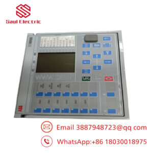
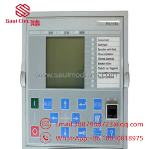
The ABB REM610 is a dedicated, numerical motor protection relay engineered specifically for the protection, control, and monitoring of asynchronous medium and large-sized industrial motors. Deployed across demanding process sectors—such as petrochemical refining, water treatment pumping, marine propulsion, and heavy mining conveyors—this compact relay monitors phase currents and thermal accumulation trends. It actively shields motor stators and rotors from premature insulation degradation, mechanical overloading, and catastrophic winding failure.
At the core of the REM610 is an advanced, micro-controller-driven thermal replica algorithm (ANSI 49M). By continuously integrating true RMS phase current parameters into an internal mathematical model, the unit tracks both historical running heat generation and cooling cycles, providing reliable protection against prolonged starting phases, stall/locked rotor conditions, and repetitive hot restarts. The split configuration design employs a plug-in chassis system, facilitating straightforward module exchanges during turnaround schedules while leaving the underlying field wiring secure and undisturbed.
Comprehensive SOP Quality Control & Testing
To eliminate field initialization faults and maintain historical performance parameters, every stock REM610 processor module completes our strict quality validation routine prior to shipment.
1. Inbound Inspection & Traceability
- Hardware Variant Decode: The exact ordering matrix (such as power supply limitations and communication bus compatibility) is verified against the laser-etched side stickers and embedded EEPROM parameters.
- Chassis Physical Integrity: We inspect the front plastic frame bezel, text displays, terminal block pin tracks, and internal shielding plates for mechanical alignment or wear.
- Component-Level Review: Printed circuit boards are scanned under specialized lighting to confirm that capacitors show no swelling and that optical isolator paths remain completely clear of film.
2. Live Functional Testing
- Test Setup: The REM610 draw-out module is inserted into a calibrated master housing chassis on a specialized protection evaluation bench.
- Power-On Initialization: The unit is energized across its specified voltage range. The technician verifies that the green “Ready” LED illuminates and that the local LCD text lines clear their self-diagnostic checks.
- Secondary Current Injection: Balanced and unbalanced three-phase currents are injected into the transformer blocks using a secondary injection test set. We verify measurement scaling values on the front HMI to confirm that accuracy deviates by less than ±1%.
- Thermal Curve Trip Verification: We inject an overload profile equivalent to 2.5 \times I_n to trace the thermal integration algorithm curve, confirming that the physical trip relay contact fires exactly within the designated millisecond window.
- Reporting: A comprehensive QA certificate is generated, logging secondary current tracking parameters, serial data markers, and software version codes.
3. Electrical Parameter Testing
- Dielectric Isolation Verification: Using a Fluke 1507 insulation tester set to 500 V DC, insulation levels between binary inputs, phase current links, and the central grounding block are measured to ensure barriers read >10 MΩ.
- Ground Continuity: The bonding path between the outer case grounding pad and the internal circuit card paths is tested to confirm it reads under 0.1 Ω.
4. Firmware & Configuration Verification
- Software Version Alignments: System firmware records are checked. The device parameters are cleared back to default factory baseline matrices unless custom parameter sets are requested by the customer.
- HMI Keypad Response: Front selection pushbuttons are exercised sequentially to confirm that menus navigate cleanly and that local parameter adjustments register correctly.
5. Final QC & ESD Packaging
- Authorization Labeling: A dated QA inspection seal is applied across the seam of the plug-in housing module.
- ESD Safe Bagging: The relay is placed into a thick, silver anti-static shielding bag to protect it from field static discharges.
- Armor Boxing: The packaged relay is secured between high-density foam cushioning elements inside a rigid double-wall corrugated box designed for secure global transit.
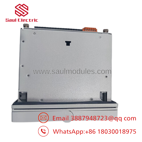
- REM610
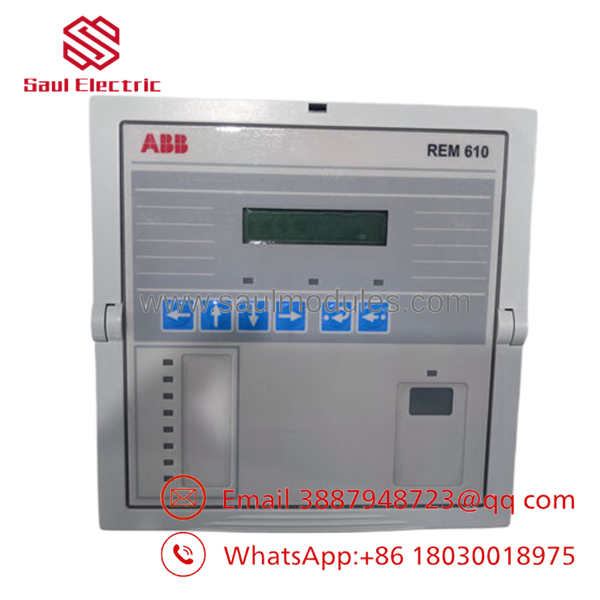
- REM610
Technical Pitfall & Motor Replacement Survival Guide
Replacing or retrofitting an engine or pump protection relay requires attention to thermal variables and wiring safety. Review these five common field installation errors to prevent nuisance trips and equipment damage.
1. Failure to Account for Existing CT Secondary Tap Mismatches
- ❗ The Risk: The has separate rear terminal locations for 1 A and 5 A secondary current transformer (CT) lines. If a replacement relay is wired into the 5 A terminals while the field CTs output a 1 A nominal signal, the relay will read currents at one-fifth of their actual value. This renders the thermal replica and overcurrent protection loops non-functional, which can cause the motor to burn out without triggering a trip.
- 🛠| Mitigation: Identify your site’s CT secondary output ratings from the switchgear schematic before landing wires. Connect the phase current wires to terminals X1.1–X1.6 matching your nominal 1 A or 5 A specifications, and verify the internal software settings match this selection.
2. Overlooking Cumulative Start Monitor Limits
- ❗ The Risk: The includes a cumulative start monitor function (ANSI 66) that limits the number of motor starts allowed within a specified time period to protect the rotor cage from thermal stress. If a new surplus relay with default factory parameters is installed without configuring this limit, operators could restart a stalled motor repeatedly, potentially cracking the rotor bars due to excessive heat build-up.
- 🛠| Mitigation: Review the motor manufacturer’s datasheet for the maximum allowable consecutive hot and cold starts. Program these limits into the ‘s parameter settings prior to commissioning the motor.
3. Drawing Out the Chassis Module Under Active Load
- ❗ The Risk: The uses a convenient draw-out design that allows the internal electronics to be removed from the outer case. While the case includes automatic short-circuiting mechanisms for the CT circuits, a worn, dusty, or bent shorting bar can fail to close. This creates an open CT circuit that generates high-voltage arcing, posing a safety risk and potentially destroying the terminal block.
- 🛠| Mitigation: Always trip and lock out the primary motor breaker before pulling the internal chassis out of its case. Use a clamp-on ammeter to confirm that zero current flows through the protection loop prior to extraction.
4. Phase Sequence Unbalance Setting Omissions
- ❗ The Risk: Medium-voltage motors are highly sensitive to phase current unbalance (I_2/I_1) caused by voltage asymmetry or phase loss, which creates a counter-rotating magnetic field that heats the rotor rapidly. If the phase unbalance function block is left disabled or misconfigured during a replacement, a single-phasing event can destroy the motor windings within minutes.
- 🛠| Mitigation: Enable the negative phase sequence/unbalance function block (ANSI 46) during setup. Set the alarm and trip thresholds according to the motor’s structural thermal rating—typically around 10–15% unbalance for standard industrial configurations.
5. Missing Parameter File Transfer
- ❗ The Risk: A replacement relay arrives with generic factory default settings. Installing it without configuring parameters specific to your motor—such as the nominal current rating (I_n), startup delay window, and thermal time constants (\tau)—will result in immediate nuisance trips during startup or a complete failure to trip during an overload.
- 🛠| Mitigation: Document all parameters from the old relay’s LCD panel, or download the settings configuration using the front-panel communication interface before removal. Manually input or download these exact parameters into the replacement unit before starting the motor.
Frequently Asked Questions (FAQ)
Can I change the communication protocol of a in the field?
Yes, by changing the rear plug-in module. The platform uses interchangeable communication modules that slide into a dedicated slot on the rear panel. If your plant is migrating from an older SPA-bus or Modbus RTU serial network to a Profibus DP system, you can replace the communication module (e.g., swapping a plastic optical module for a copper RS-485 interface card) without needing to replace the entire core relay assembly.
What is the purpose of the thermal replica function (49M) in this relay?
The thermal replica function acts as a digital twin of the motor’s thermal characteristics. Because embedded stator resistance temperature detectors (RTDs) only measure localized temperatures, they can miss rapid heating in the rotor bars during startup or stalled conditions. The ‘s thermal replica continuously calculates total heat accumulation based on the mathematical square of the true RMS current (I^2), safeguarding both the stator and rotor components.
What does the “BCH” suffix mean on a type designation code?
On standard ABB configurations, the suffix letters define the regional language package, hardware revision baseline, and terminal block layout options. Specifically, the character H denotes that the internal power supply board is the high-voltage variant, designed to operate reliably across a wide input range of 110–240 V AC or 110–220 V DC nominal distribution networks.
How does the track motor cooling when the motor is stopped?
When the motor current drops to zero, the ‘s internal thermal replica switches from its running thermal time constant to a dedicated cooling time constant (\tau_{cool}). This parameter simulates the natural thermal dissipation of the motor while at rest. This cooling tracking prevents operators from restarting a hot motor too quickly, protecting the stator winding insulation from cumulative thermal degradation.
Why choose a new surplus over a modern replacement series?
Using a new surplus allows maintenance teams to replace a failed unit directly without modifying panel cutouts, changing rear terminal wiring layouts, or updating engineering software tools. This drop-in compatibility minimizes repair downtime during critical plant turnarounds, avoiding the high engineering and labor costs associated with a full protection system upgrade.

 Start Chat


