





Description
Key Technical Specifications
| Parameter | Specification Value |
| Main Application Scope | Two-winding / Three-winding power transformers, autotransformers, shunt reactors |
| Core Protection Functions | Restrained/unrestrained differential protection, phase overcurrent, sensitive earth fault |
| Inrush/Harmonic Restraint | 2nd and 5th harmonic restraint algorithms for CT saturation handling |
| Auxiliary Power Supply | 24–250 V DC (\pm 20%) or 100–240 V AC (\pm 20%), 50/60 Hz |
| Analog CT / VT Inputs | Configurable analog input modules supporting 1 A / 5 A CTs and 100 V / 110 V VTs |
| Communication Protocols | IEC 61850-8-1, Modbus, DNP3, IEC 60870-5-103 |
| Binary Inputs / Outputs | Highly flexible, expandable I/O cards with high-speed trip contacts |
| Fault Recording Capability | Built-in oscillography (up to 10 seconds per disturbance record) and 1,000-event log |
| Local Interface (LHMI) | Full graphical LCD back-lit display with dynamic mimic diagrams and control keys |
| Enclosure Protection Rating | IP54 front panel sealing, IP20 rear housing termination point |
| Operating Temperature | −25 to +55 °C (−13 to +131 °F) continuous operation |
Product Introduction
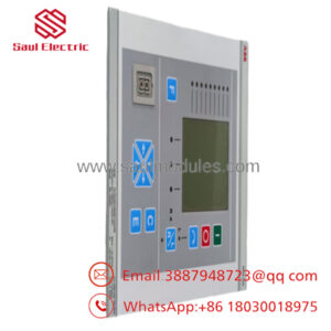
The ABB RET670 (1MRK004816-AC) is an advanced substation-grade Intelligent Electronic Device (IED) belonging to the Relion® 670 series, engineered for the comprehensive protection, control, and monitoring of large-scale power transformers and shunt reactors. This module operates on high-speed mathematical algorithms to perform multi-winding differential protection, phase overcurrent calculations, and breaker failure oversight within critical utility grids and heavy industrial substations.
Designed from the ground up to realize the core values of the IEC 61850 substation automation standard, the 1MRK004816-AC hardware variant provides interoperable horizontal peer-to-peer GOOSE messaging for fast trip coordination without hardwiring. Its automatic current transformer (CT) ratio matching and integrated vector group compensation eliminate the need for traditional, complex interposing physical hardware, rendering it a foundational asset for grid reliability and automation.
-
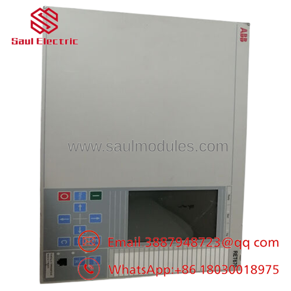
- RET670 1MRK004816-AC
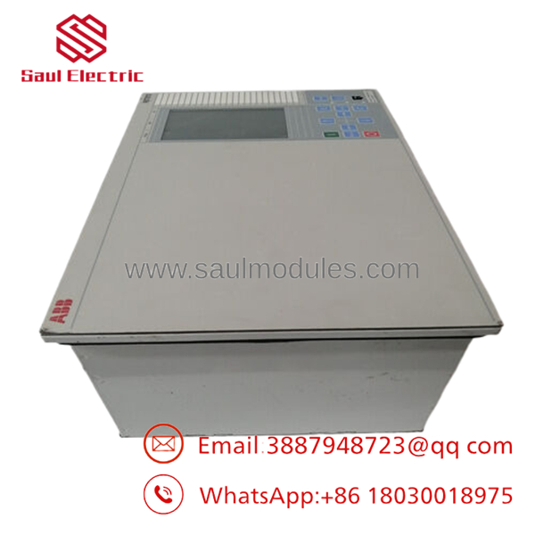
- RET670 1MRK004816-AC
Installation & Configuration Guide
Stage 1: Pre-Installation Preparation (Estimated Time: 25 minutes)
- ⚠️ Safety First: Changing or working on substation protection IEDs carries life-safety risks. Ensure the targeted high-voltage circuit breakers are locked out, isolated, and visibly grounded. Short-circuit all secondary current transformer (CT) circuits at their dedicated shorting terminal blocks before disconnecting any analog inputs to prevent fatal open-circuit voltages.
- Tools Required: Grounded anti-static wrist strap, calibrated torque screwdriver (M4/M5 binding screws), digital multimeter, and a laptop running PCM600 Protection and Control IED Manager software with a dedicated USB front-connection cable.
- Data Backup: Launch PCM600 and establish an active path to the running relay. Perform a full configuration upload (
.pcmiformat), archiving all parameters, custom logic schemes, disturbance recordings, and calibrated CT/VT phase correction profiles.
Stage 2: Removing the Old Module (Estimated Time: 15 minutes)
- Confirm that secondary CT shorting bars are properly engaged.
- Isolate and verify zero voltage on the auxiliary power supply terminals using your multimeter.
- Loosen and disconnect the compression screw terminals or plug-in terminal block assemblies from the rear of the device. Label every cable harness bundle with its physical module destination slot ID.
- Extract any optical fiber communication lines from their LC/ST bayonet ports, capping them immediately to protect the fiber core from dust contamination.
- Support the device body from the bottom while loosening the panel mounting screws. Slide the chassis straight out out of the cut-out slot or standard 19-inch rack enclosure.
- ⚠️ Note: Keep the uninstalled unit secure for structural validation until the replacement system is fully functional.
Stage 3: Installing the New Module (Estimated Time: 20 minutes)
- Verify that the hardware order configuration string on the side label of the new 1MRK004816-AC perfectly matches the requirements of your substation wiring schematic.
- Insert the relay assembly through the panel cutout smoothly to avoid pinching structural wire bundles behind the panel face.
- Secure the front panel flange to the rack frame using standard mounting screws, tightening them evenly to prevent physical alignment stress.
- Re-insert the rear compression terminal blocks carefully, ensuring correct terminal alignment, and torque all connection screws to factory specification limits.
- Reconnect fiber optic patches to their designated communication module transceiver channels.
Stage 4: Power-On & Testing (Estimated Time: 35 minutes)
- Switch on the auxiliary operating power supply circuit breaker.
- Monitor the local HMI assembly screen. The unit runs internal flash diagnostics; the green “Ready” LED must light up steadily, and the red “Fail” LED must stay off completely.
- Connect your engineering laptop to the front optical/USB serial diagnostics port. Using PCM600, write the previously archived
.pcmisoftware configuration map into the new IED memory. - Re-verify the target IEC 61850 IP configuration address settings and check that GOOSE network communications to neighboring bay modules register normal operation.
- Carefully open the secondary CT shorting bars. Perform a primary side inject test or live line check under low load to verify phase current angles, magnitudes, and correct differential balance calculation outputs on the LCD before introducing primary tripping logic back to the circuit breakers.
- ⚠️ Troubleshooting Note: If a “Hardware Mismatch” fault code triggers on the display screen, use PCM600 to poll the unit hardware profile and verify that your software parameter model matches the actual physical I/O boards populated inside the chassis slots.
Frequently Asked Questions (FAQ)
Can the RET670 be hot-swapped while the transformer line is fully energized?
No, the RET670 is a comprehensive intelligent substation chassis, not a standard modular industrial PLC card. Removing the unit or pulling its terminal blocks while under load creates an immediate hazard because open-circuiting live current transformers (CTs) will generate lethal high-voltage arcs. The primary transformer path or the secondary protection circuits must be completely isolated and bypassed before any physical extraction occurs.
What is the purpose of the 5th harmonic restraint feature included on this device?
The 5th harmonic restraint algorithm prevents the RET670 from executing a nuisance trip during periods of overexcitation on the power transformer, which typically occurs during major grid voltage swings or sudden load drops. By analyzing the ratio of the 5th harmonic component to the fundamental frequency, the relay confidently distinguishes between a dangerous internal winding short-circuit fault and a temporary, non-damaging overfluxing condition.
Our original model is an older version. Is this 1MRK004816-AC unit compatible?
The 1MRK004816-AC is a standardized hardware profile code within the global Relion 670 series platform. While it provides backward-compatible performance for underlying multi-winding differential applications, you must use ABB’s PCM600 software tool to verify that the target firmware baseline and parameter mappings correspond correctly to your existing substation template library before downloading the protection configuration.
How are the internal event records and oscillography files stored during a sudden loss of auxiliary power?
The contains an internal non-volatile memory layout that instantly commits event lists, sequence-of-events (SOE) logs, and high-resolution fault waveforms to persistent storage without requiring an onboard backup cell. The records will remain completely intact and accessible for system analysis as soon as auxiliary power is restored to the chassis.
Why is there a significant price range variation for units on the open market?
The base part number defines the physical frame and modular structural components, but the final commercial value of a customized is highly dependent on the internal software license keys activated within the unit (such as specific distance protection packages, breaker control counts, or advanced monitoring configurations). Our New Surplus inventory offers standard pre-configured functional blocks at substantial discount rates, allowing utility teams to bypass extended factory lead times.


 Start Chat


