





Description
Key Technical Specifications
| Parameter | Value |
| Manufacturer | ABB |
| Model Designation | SCM/S1.1 |
| Product ID | 2CDG110024R0011 |
| Bus System | KNX (TP) / EIB |
| Number of Evaluated Zones | Up to 64 distinct zones |
| Relay Output | 1 potential-free contact, 6 A switching capacity |
| Acoustic Signaling | Internal piezo buzzer for fault/alarm indications |
| Local Status Displays | 3 LEDs (Red: Alarm, Yellow: Set/Unset, Green: Operation) |
| Degree of Protection | IP20 conforming to EN 60 529 |
| Mounting Configuration | 35 mm DIN Rail (DIN EN 60 715), occupies 2 modules (36 mm width) |
| Net Weight | 0.08 kg |
| Operating Temperature | −5 to +45 °C |
Product Introduction & Supply Chain Strategy
The ABB SCM/S1.1 (2CDG110024R0011) is an advanced security logic module designed for integration within automated building infrastructures running on the KNX/EIB fieldbus standard. It serves as a decentralized logic manager, consolidating inputs from up to 64 independent zones—including motion detectors, emergency triggers, lock monitors, and tamper sensors. By processing this status data locally, the card initiates programmed reactions, coordinates telephone dialers, activates acoustic warnings via its onboard buzzer, or triggers external sirens through its robust 6 A output relay.
From an inventory and supply chain standpoint, choosing this product as a New Surplus asset optimizes your Total Cost of Ownership (TCO). While standard field controllers are flexible, using secondhand or rebuilt parts in your infrastructure exposes your facility to dangerous blind spots. Over time, internal relays and electronic warning systems break down due to voltage fluctuations and constant use. Investing in clean, factory-certified surplus stock avoids the threat of sudden sensor bus failure and protects your automated systems without forcing an expensive upgrade to current network standards.
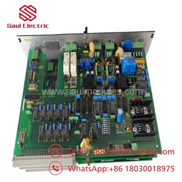
- SCM-1
Installation & Configuration Guide
Stage 1: Pre-Installation (Prep & Safety)
- Power down the primary 230 V AC supply line leading to any adjacent control relays and isolate the KNX bus line to prevent hot-plugging damage.
- Put on a standard ESD wrist strap and connect the ground lead to the metal DIN enclosure frame.
- Record the physical node addressing scheme and document the terminal configuration of the external output relay connections.
Stage 2: Removal
- Unclip the dark red/black KNX bus connection terminal block from the base of the housing using a small slot screwdriver.
- Disconnect the primary terminal wiring connected to the internal 6 A alarm relay outputs.
- Release the quick-snap DIN rail locking tab located at the base of the chassis, then pivot the module outward to pull it clear of the 35 mm mounting rail.
Stage 3: Installation (Clone & Seat)
- Mount the new surplus SCM/S1.1 on the 35 mm DIN rail, applying uniform pressure until the plastic locking clip snaps firmly over the rail edge.
- Reconnect the red/black KNX bus lines into their dedicated, polarized sockets on the module frame.
- Secure the auxiliary alarm output wiring to the upper terminal screws, ensuring you torque each connection to prevent localized high-resistance joints.
Stage 4: Power-On & Testing
- Re-energize the KNX bus power supply and verify that the green Operation LED lights up steadily.
- Use the Engineering Tool Software (ETS) interface to confirm communication with the device node and verify that it matches your physical physical zone map.
- Trigger a test zone input to check that the yellow Set/Unset indicators change appropriately and verify the response of the internal acoustic buzzer.
Firmware/Software Versions & Upgrade Notes
The SCM/S1.1 handles data via specific application programs embedded inside the internal non-volatile EEPROM memory. System parameter changes and operational logic mapping are handled via the standard Engineering Tool Software (ETS) framework.
When replacing an older unit, always verify that the product database version uploaded inside your ETS project exactly matches the hardware revision of the new surplus part. Mismatches between your software database files and the hardware revisions can prevent proper memory writes during commissioning. This can block access to the full 64-zone memory space or cause unexpected timeouts on the twisted-pair network. Avoid flashing new logic addresses to the component during high-traffic network periods to ensure you don’t corrupt the core boot blocks.
Frequently Asked Questions (FAQ)
Is this SCM/S1.1 security module an original new unit or a repaired component?
This module is a guaranteed New Surplus item. It has never been deployed in any automated system, mounted on a live field rail, or subjected to electrical wear. Every unit undergoes strict quality verification checks at our warehouse facility to ensure zero-hour factory performance, and we do not supply refurbished or used gear.
Why does a new surplus module cost more than a standard refurbished model?
Refurbished security components carry serious liabilities, such as contact oxidation on the internal 6 A output relay and degradation of the internal acoustic signaling system. A sudden failure of an old security part can cause false alarms or leave critical areas completely unmonitored. Sourcing a new surplus component avoids these reliability problems, protecting your facility from unexpected production downtime and safety risks.
Does the SCM/S1.1 module require an extra external power supply connection?
No. The primary logic circuitry and communication functions run directly on the low-voltage DC power supplied by the KNX twisted-pair (TP) bus connection line. However, if you choose to route external signaling devices through the internal 6 A relay contact, you will need to provide separate power loops for those external lines.
Can I hot-swap the KNX bus terminal connection while the network loop is live?
While the KNX bus is theoretically hot-pluggable, doing so on security modules is not recommended. Plugging in the bus connection while power is applied can trigger unexpected inductive voltage jumps. This can cause false alarm calls across the network or corrupt the local node configuration data during initialization.
What warranty terms cover this new surplus industrial hardware?
We provide a comprehensive 1-year warranty on this New Surplus SCM/S1.1 module, starting from the day it leaves our warehouse. This warranty matches the coverage of original factory components, giving your facility management team dependable protection and peace of mind.


 Start Chat


