





Description
Key Technical Specifications
| Parameter | Value |
| Manufacturer | ABB |
| Model Designation | SDCS-PIN-4 (Coated version: SDCS-PIN-4-COAT) |
| Primary Part Numbers | 3ADT314111P4103 / 3ADT314100R1001 |
| Application Compatibility | ABB DCS800 DC Industrial Drives (Frames D1, D2, D3, D4) |
| Auxiliary Supply Voltage | 115 to 230 V AC (Internal automatic adjustment) |
| Integrated Functions | Onboard Field Exciter, Armature Firing, System Power Supply |
| Isolation Design | High-ohmic voltage measurement isolation for DC and AC lines |
| Protection Systems | Onboard fuses, integrated thyristor protection snubber circuit |
| Dedicated Output | 1 integrated normally-open relay contact (controlled via DO8 / Connector X96) |
| Feedback Interfaces | Current transformer (CT) interface & PTC heat sink thermistor input |
| Operating Temperature | −40 to +70 °C |
| Net Weight | 0.80 kg |
Product Introduction & Supply Chain Strategy
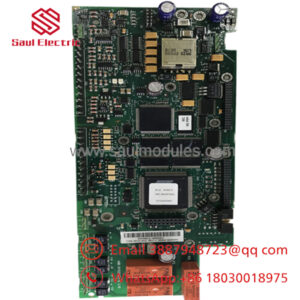
The ABB SDCS-PIN-4 is the main circuit power interface board positioned between the high-power thyristor bridge and the SDCS-CON-4 control card in DCS800 industrial DC drives. This multifaceted board contains the internal drive power supply, the armature firing pulse circuit, an onboard field exciter, and protective snubber circuits. It provides isolated high-ohmic feedback for AC line and DC motor voltages, making it the central hardware link for speed and current regulation loops in heavy applications like metal rolling mills, extruders, and mine hoists.
From a procurement perspective, maintaining this component as an absolute New Surplus item is essential for minimizing your Total Cost of Ownership (TCO). Because the SDCS-PIN-4 sits directly above the main thermal heat sinks, it is subjected to continuous thermal cycling and intense electrical stress. Sourcing a refurbished or second-hand replacement card introduces severe risks, as aged gate-firing circuits and heat-stressed snubber resistors can fail silently under full load. Investing in zero-hour surplus hardware ensures factory-level pulse symmetry and isolation barriers, preventing premature drive failure and catastrophic production downtime.
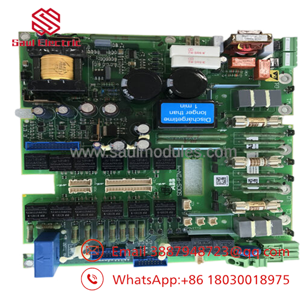
- SDCS-PIN-4
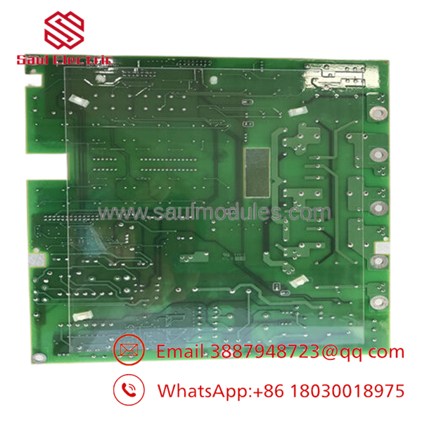
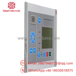
- SDCS-PIN-4
Installation & Configuration Guide
Stage 1: Pre-Installation (Prep & Safety)
- Isolate the main 3-phase AC input supply and all auxiliary control power lines feeding the drive cabinet.
- Use a digital multimeter to verify that input terminals U1, V1, W1 and DC outputs C1 and D1 read close to 0 V against the chassis frame.
- Put on a grounded ESD wrist strap before touching the module.
- Document the exact position of hardware jumper S1 and note the layout of the three flat ribbon cables connecting to the controller card tray.
Stage 2: Removal
- Unplug the flat ribbon communication cables (X12, X13, etc.) and disconnect the heavy-gauge wires from the field current and auxiliary voltage terminal blocks.
- Carefully loosen the mechanical fixing screws that secure the electronic tray and open it along its hinges to reveal the underlying board.
- Remove the board retaining screws keeping the card firmly seated against the internal thyristor busbar connections, ensuring no hardware drops into the power stack.
Stage 3: Installation (Clone & Seat)
- Configure jumper S1 on the new surplus board. Leave S1 open for automatic 115/230 V AC auto-scaling, or bridge it to lock the power input to a fixed 230 V AC line.
- Seat the new board precisely onto the mounting standoffs, making sure the board achieves a low-resistance mechanical ground connection to the chassis via its fixing points.
- Reinstall all mechanical screws and torque them down cleanly to prevent loose contacts on high-current pathways. Reconnect the ribbon cables until they click into their sockets.
Stage 4: Power-On & Testing
- Reapply auxiliary control voltage while keeping the main 3-phase line power locked out.
- Verify that the internal power supply section initializes correctly and check that digital output 8 (Relay DO8 at connector X96) operates as intended.
- Ensure the drive display panel registers no armature or field feedback faults before safely re-energizing the main power circuits for a low-speed motor rotation check.
Firmware/Software Versions & Upgrade Notes
The functions as a hardware-level execution and signal-routing board and does not contain programmable flash firmware or firmware chips. All drive logic and tracking software reside on the matching SDCS-CON-4 control board hanging on the hinged electronic tray.
However, when installing this new surplus card, you must confirm that the current transformer (CT) burden scaling parameters in your drive firmware match your physical power stack configuration. If the revision layer of the new interface board alters the gate-firing characteristics relative to your previous card configuration, you must execute a full armature and field current auto-tuning sequence via the DCS800 control panel. This auto-tuning ensures the control firmware aligns with the physical pulse transformer properties of the new hardware.
Frequently Asked Questions (FAQ)
Is this board factory new or a rebuilt item?
This board is a guaranteed New Surplus component. It has never been installed in a working drive, run in a production line, or subjected to electrical repair. It is stored in its original packaging and opened only for our warehouse inbound inspection and quality verification. We enforce a strict policy against supplying used or refurbished hardware.
Why is the pricing for this new surplus module higher than a standard refurbished model?
Refurbished pulse interface boards carry massive hidden risks because their integrated snubber resistors and pulse transformers age under high ambient operating temperatures. A failure in a refurbished board’s isolation section can let high-voltage armature spikes leak straight into the low-voltage microprocessor circuits, destroying the entire electronic tray. Buying a new surplus component completely eliminates this risk, providing a fresh 10–15 year operational life and protecting your plant from expensive unplanned downtime.
What does the onboard hardware jumper S1 control?
Jumper S1 sets the operational profile of the internal power supply. If left open, the power supply automatically scales its parameters to handle either 115 V AC or 230 V AC auxiliary inputs. Bridging jumper S1 overrides this automatic adjustment, locking the incoming power profile strictly to a fixed 230 V AC system.
What drive frames can use this specific power interface card?
The card is engineered explicitly for ABB DCS800 industrial DC drive units utilizing the D1, D2, D3, and D4 frame sizes. Always verify your specific frame classification on the drive rating plate before replacing this module.
What type of warranty protection do you offer on this hardware?
We provide a comprehensive 1-year warranty on this New Surplus module, starting from the day it leaves our shipping center. This policy matches original OEM warranty parameters, providing dependable safety and security for your spare parts inventory.

 Start Chat


