





Description
Key Technical Specifications
| Parameter | Value / Specification |
| Part Number | SDCS-PIN-4B / 3BSE004939R0001 |
| Application | DCS500 / DCS600 DC Drives (Frames C3, C4, D1–D4) |
| Input Nominal Voltage (U_1) | 230 V AC to 1,000 V AC (50 / 60 Hz) |
| Gate Drive Output | 6-pulse channel firing signals (configurable for 12-pulse configurations) |
| Auxiliary Power Supply Inputs | +24 V DC, +/-15 V DC from SDCS-POW board |
| Isolation Rating | Galvanic isolation via pulse transformers up to 1,000 V AC |
| Measurement Functions | Integrated AC line voltage synchronization and DC bus voltage feedback |
| Operating Temperature | 0 to +55 °C |
| Storage Temperature | −40 to +70 °C |
| Weight | 1.15 kg |
Product Introduction
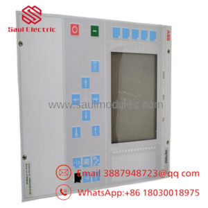
The ABB SDCS-PIN-4B is a dedicated power supply and pulse transformer board utilized primarily within the DCS500 and DCS600 DC converter drive architectures. It serves as the critical hardware link between the low-voltage control electronics (such as the SDCS-CON board) and the high-power SCR/thyristor bridges. The board scales the incoming main AC voltage down for synchronization tracking while simultaneously driving the thyristor gates via robust, galvanically isolated pulse transformers.
Engineers select the SDCS-PIN-4B for retrofits and emergency maintenance because it integrates both the voltage measurement network and the pulse amplification circuitry onto a single PCB. This consolidated layout reduces internal drive wiring complexity and minimizes electromagnetic interference (EMI) susceptibility. This board ensures reliable thyristor commutation across wide supply voltage variations, making it a critical component for heavy industrial applications like metal rolling mills, paper machines, and mine hoists.
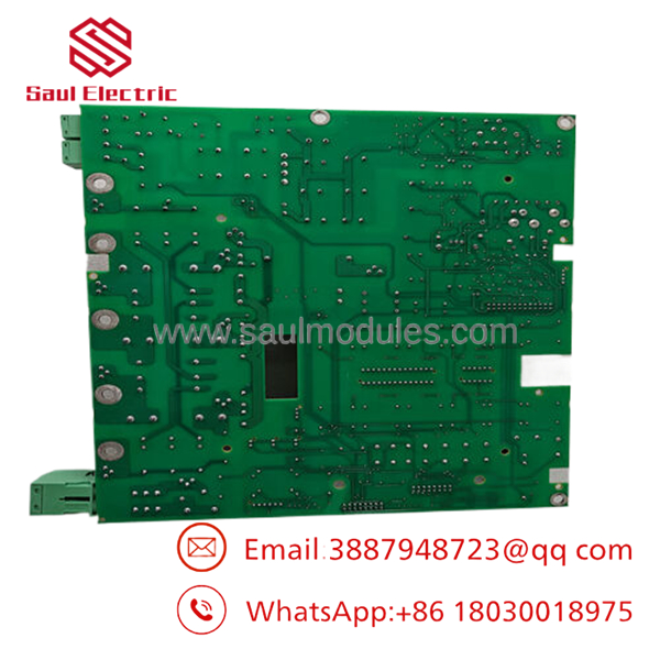
- SDCS-PIN-4B
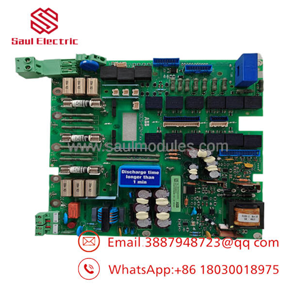
- SDCS-PIN-4B
Installation & Configuration Guide
Stage 1: Pre-Installation Preparation (Estimated Time: 10 minutes)
- ⚠️ Safety First: Disconnect and isolate all main AC power feeds (230 V–1,000 V) and auxiliary 24 V DC control voltages supplying the drive. Lock out and tag out (LOTO) the main circuit breaker. Wait at least 5 minutes for internal drive capacitors to discharge to safe levels. Use a calibrated multimeter to verify zero voltage at the main UVW input terminals and the DC bus before touching any internal boards.
- Tools Required: Grounded ESD wrist strap, Pozidriv PZ2 screwdriver, Fluke 115 multimeter, fine-tip permanent marker or wire labels, smartphone.
- Data Backup: The SDCS-PIN-4B does not store drive firmware parameters (parameters reside on the SDCS-CON board). However, you must photograph and document all physical jumper configurations (S1, S2, etc.) and tap settings on the board being replaced to guarantee proper scaling of the synchronization voltages.
Stage 2: Removing the Old Module (Estimated Time: 10 minutes)
- Open the drive cabinet enclosure door and remove any plastic protective shields covering the control card cage.
- Label each ribbon cable and discrete wire harness connected to the board to prevent incorrect reassembly.
- Carefully disconnect the flat ribbon cables from the control board interfaces and unplug the high-voltage synchronization wire plugs. Do not pull directly on the wire strands; grip the plastic connector housings.
- Loosen and remove the retaining screws securing the PCB to the drive chassis ground pillars.
- Pull the board straight out from its mounting position. Inspect the underlying chassis standoffs for any signs of electrical arcing or contamination.
Stage 3: Installing the New Module (Estimated Time: 10 minutes)
- Ensure your ESD wrist strap is connected to a verified earth ground. Remove the new board from its static shielding bag.
- Configuration Clone (Crucial): Compare the physical jumpers and hardwired selector links on the old board with the new board. You must move the jumpers on the new board to mirror the exact positions of the old board. These jumpers set the synchronization voltage matching ranges (e.g., 400 V vs. 690 V). Incorrect settings will cause instant overvoltage faults or catastrophic thyristor misfiring.
- Position the board over the mounting pillars and secure it using the original screws. Ensure all ground trace pads on the board frame make tight contact with the metallic standoffs to guarantee low-impedance grounding.
- Reconnect all ribbon cables and high-voltage wire harnesses. Verify that all latching connectors are fully seated and clicked into place.
📋 Self-Checklist:
- [ ] Jumper links S1/S2 match the original site configuration precisely.
- [ ] All high-voltage measurement plugs are locked in their correct sockets.
- [ ] Grounding screws are tight, and no wire strands are pinched under the board.
Stage 4: Power-On & Testing (Estimated Time: 15 minutes)
- Perform a resistance check across the auxiliary power rails (+24 V, +15 V, -15 V) to ground using a multimeter to ensure no short circuits exist.
- Re-apply auxiliary control power only (do not energize the main AC power bridge yet).
- Verify that the drive’s control panel boots normally without displaying immediate power supply rail faults.
- Safely energize the main AC supply lines.
- Use the drive configuration tool or keypad to monitor the line synchronization values. Check if the measured line voltage matches the actual incoming grid voltage.
- Run the motor under a decoupled, low-load condition to verify stable gate firing signals and smooth armature current control.
- ⚠️ Troubleshooting Note: If the drive immediately trips on a “Line Sync” or “Phase Loss” fault upon main power application, immediately de-energize the system. Re-verify the jumper settings on the that dictate the voltage scaling network, as the board is likely reading the line voltage outside of expected limits.
Frequently Asked Questions (FAQ)
Can I hot-swap the board while the control power is active?
No, absolutely not. Attempting to hot-swap this board will likely destroy the pulse transformer circuits and damage the upstream SDCS-CON control board via transient voltage spikes. The routes main supply synchronization voltages that can range up to 1,000 V AC, alongside critical DC power rails. Always kill both the main power and auxiliary control supplies before servicing this component.
How do I know if my existing board failure is due to the pulse transformers or the thyristor itself?
When a thyristor faults or shorts out, it frequently sends a high-voltage back-feed through the gate lead, which destroys the corresponding pulse transformer channel on the board. If you notice burnt resistors or cracked transformer casings near the gate outputs on the board, do not simply swap the board. You must test the external thyristor modules with a multimeter (checking gate-to-cathode and anode-to-cathode resistance) before installing the new board, or you risk immediately destroying the replacement unit.
Are the jumper settings identical across all DCS500 and DCS600 applications for this board?
No, they are highly dependent on your specific line voltage. The uses onboard hardware jumpers to adapt its internal resistor measurement networks to your specific incoming plant grid voltage (such as 380 V, 460 V, 500 V, or 690 V). If you install a factory-default board without matching these jumpers to your original board’s positions, the drive will read incorrect synchronization data, leading to misfiring or immediate overvoltage/undervoltage trips.
What is the difference between an and an SDCS-PIN-4A?
The is a later revision that features updated component layouts and improved insulation resistance properties compared to the older “4A” version. The “4B” version provides direct backward compatibility with most drive configurations that used the “4A,” provided that you match the physical jumper positions and trace terminal layouts exactly. Always cross-reference your specific drive frame size (C3 to D4) in the OEM technical manual to ensure exact fitment.
Why is the price of this surplus board lower than ordering straight from the factory?
As industrial automation systems migrate toward modern AC drive solutions, stock for legacy DC components like the DCS500 series becomes classified as “New Surplus” or warehouse overstock. We acquire these parts directly from plant liquidations, system upgrades, and cancelled projects. Because we bypass traditional OEM distribution markups, we can pass these direct cost savings along to you while verifying functionality through comprehensive testing.


 Start Chat


