





Description
Key Technical Specifications
| Parameter | Value |
| Manufacturer | ABB |
| Model Designation | SNAT604IFS |
| Application Compatibility | Sami MegaStar and legacy high-power AC/DC converter assemblies |
| Input Supply Channels | Low-voltage AC or DC raw auxiliary rail connection |
| Onboard Power Outputs | Multiple isolated DC voltage rails for internal control logic |
| Interface Driving Logic | High-speed fiber optic or ribbon interface line connections |
| Pulse Shaping Properties | Integrated pulse transformer arrays for uniform gate turn-on |
| Electrical Isolation | Galvanic barrier shielding control logic from power-stack transients |
| Mounting Orientation | Internal slide rack or chassis standoff mounting |
| Operating Temperature | 0 to +55 °C |
| Storage Temperature | −40 to +70 °C |
Product Introduction & Supply Chain Strategy
The ABB SNAT604IFS is a critical internal power supply and gate interface board engineered for legacy heavy-duty industrial drives, specifically within the Sami MegaStar family and specialized high-power converter stacks. This multi-layered circuit board converts raw auxiliary inputs into stable, isolated DC voltage rails required by local processing cards while simultaneously routing critical gate-firing commands to large-scale thyristor or GTO modules. Its design prioritizes low inductive trace loops and tight pulse synchronization to ensure balanced switching across high-current phases.
From an asset-management perspective, maintaining this component as a New Surplus asset optimizes your Total Cost of Ownership (TCO). Because the SNAT604IFS acts as both a local power supply and a gate driver, it is exposed to continuous heat dissipation and electrical stress. Sourcing a refurbished or second-hand alternative introduces significant risk; aged onboard transformers and filter capacitors degrade silently over time, which can lead to firing asymmetries, premature thyristor degradation, or total phase shorts. Securing factory-clean, zero-hour surplus hardware isolates your high-power processes from these hidden reliability pitfalls.
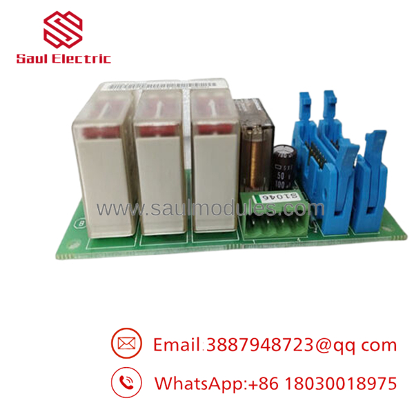
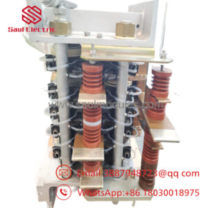
- SNAT604IFS
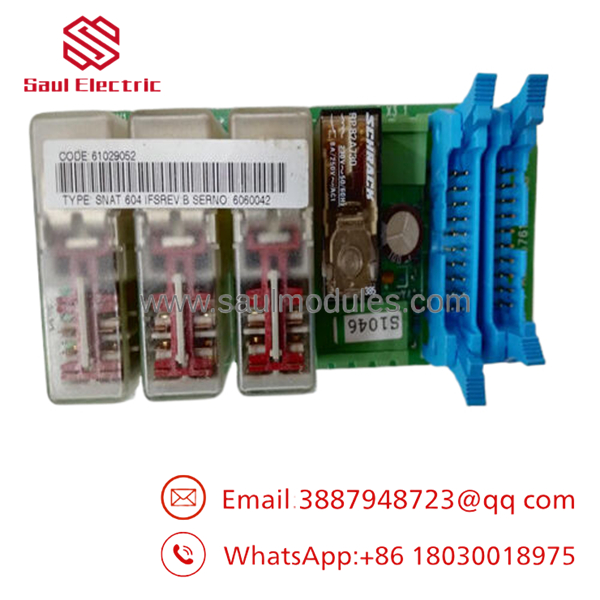
- SNAT604IFS
Installation & Configuration Guide
Stage 1: Pre-Installation (Prep & Safety)
- Execute full lock-out/tag-out (LOTO) protocols on the drive’s primary 3-phase incoming circuit breaker and all auxiliary control power lines.
- Confirm that all high-voltage DC bus capacitors have discharged completely by testing the terminals with a properly rated digital multimeter (verify 0 V).
- Put on a grounded ESD wrist strap connected directly to the enclosure frame earth ground.
- Document and label all incoming wires, fiber optic cables, and ribbon harnesses attached to the failing board.
Stage 2: Removal
- Unclip the fragile fiber optic cables and multi-pin ribbon assemblies from their sockets, taking care not to twist or bend the connectors.
- Disconnect the auxiliary power input lines and gate-firing distribution wires from the screw terminal strips.
- Loosen and remove the mechanical mounting fasteners holding the card onto the internal chassis standoffs, ensuring no screws fall into the lower power stack.
Stage 3: Installation (Clone & Seat)
- Match any configuration jumpers or DIP switches on the new surplus SNAT604IFS card to mirror the settings of the original board exactly.
- Carefully set the new card onto the mounting standoffs, ensuring all screw holes line up without forcing the board into a twist or mechanical strain.
- Tighten all mounting hardware to ensure proper chassis ground paths, and plug all ribbon and fiber optic cables back into their keyed positions until they click.
Stage 4: Power-On & Testing
- Re-apply auxiliary control power while keeping the primary 3-phase line isolated.
- Measure the onboard DC voltage test points with a digital multimeter to confirm that all internal power distribution rails are stable and within specification.
- Check the central drive diagnostic interface to verify that all communication paths are clear of faults before safely re-energizing the main power circuits for an operational test run.
Firmware/Software Versions & Upgrade Notes
The operates as a hardware-level power converter and gate-firing signal routing hub. It does not include an independent programmable microprocessor, meaning it does not run application code or require firmware flash updates.
However, because this board operates inside complex, high-power legacy drives, it is critical to match the exact hardware revision suffix (e.g., IFS, or specific PCB print runs). Minor revision changes over time can adjust the internal resistance values of the gate-drive path to match specific generations of thyristor modules. When substituting a new surplus board, you should perform a standard gated pulse diagnostic check through the drive’s main control processor to confirm that pulse shape, duration, and rise times align with your power stack’s requirements before running under full load.
Frequently Asked Questions (FAQ)
Is this board factory new, or is it a refurbished item?
This board is a guaranteed New Surplus component. It has never been deployed in an active drive system, run in a production line, or subjected to field repairs. The card has been kept in a climate-controlled environment and opened exclusively for our warehouse quality check and inbound inspection. We do not sell used or refurbished hardware.
Why should we spend more on a New Surplus module when cheap refurbished options are available online?
Refurbished gate interface boards carry serious hidden liabilities because their integrated pulse transformers and capacitors age under high thermal stress and degrade silently over time. A failure on a refurbished board’s gate circuit can cause asymmetrical firing or a misfire under heavy load. This can instantly destroy expensive power thyristors and cost your plant tens of thousands of dollars in emergency downtime. Buying new surplus units ensures maximum factory precision and isolates your process from unexpected downtime.
Does the require parameter adjustments or programming out of the box?
No. Because the card does not have a local microprocessor, it does not hold software logic or require programming. Your only requirement is to verify that any hardware jumpers or DIP switches match the original board’s settings exactly before you apply power to the unit.
Can this board be replaced while other sections of the drive rack are powered up?
No. The does not support hot-swapping. Pulling or inserting this board while control power is applied can trigger sudden voltage arcs, ruin the internal connector traces, and cause destructive voltage spikes that can permanently damage the drive’s main processing unit.
What kind of warranty coverage applies to this hardware component?
We provide a comprehensive 1-year warranty on this New Surplus board, starting from the day it leaves our warehouse facility. This warranty matches the coverage terms of standard factory components, ensuring reliable security for your spare parts inventory.


 Start Chat


