





Description
Key Technical Specifications
| Parameter | Value |
| Manufacturer | ABB / Bailey Controls |
| Model Designation | SPASO11 |
| Product Series | Infi 90, Symphony Harmony Distributed Control System (DCS) |
| Module Classification | Analog Input Slave Board |
| Input Channels | 15 distinct analog inputs (optimized for RTD and Thermocouple sensors) |
| A/D Resolution | 12-bit analog-to-digital conversion |
| Isolation Barrier | Galvanic channel-to-system isolation up to 500 V DC |
| Power Consumption | Typical 4.5 W drawn directly from the system module backplane |
| Current Consumption | 185 mA at +24 V DC |
| Communication Bus | Dedicated internal slave bus link to master processor |
| Operating Temperature | 0 to +70 °C |
| Relative Humidity | 5% to 95% (non-condensing) |
Product Introduction & Supply Chain Strategy
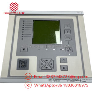
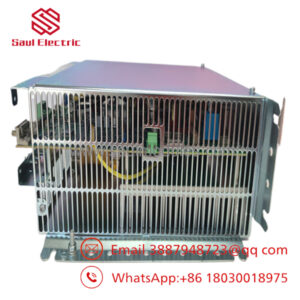
The ABB SPASO11 is a high-density, analog slave input board designed for the legacy Bailey Infi 90 and Symphony Harmony distributed control platforms. This module features 15 isolated input channels calibrated to process precise analog signals from temperature sensors, such as Resistance Temperature Detectors (RTDs) and thermocouples, deployed across harsh processing areas. The board performs localized filtering, analog-to-digital conversion, and signal conditioning before feeding clean telemetry data through the cabinet backplane to an active master controller card (such as the IMMFP12 or BRC series).
For inventory managers overseeing older DCS architectures, treating this hard-to-find part as a critical New Surplus asset helps keep your Total Cost of Ownership (TCO) low. Because the SPASO11 handles continuous, low-level analog voltages, its input filtration circuits and internal isolation channels are highly sensitive to thermal wear and power surges over decades of active service. Refurbished alternatives introduce significant operational risk: slight component drift or microscopic solder failure can cause incorrect temperature readings, leading to false process trips or delayed safety responses. Investing in factory-clean, zero-hour surplus hardware protects your critical loops from unexpected line disruptions.
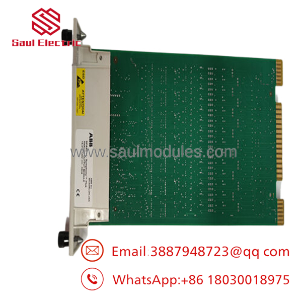
- SPASO11
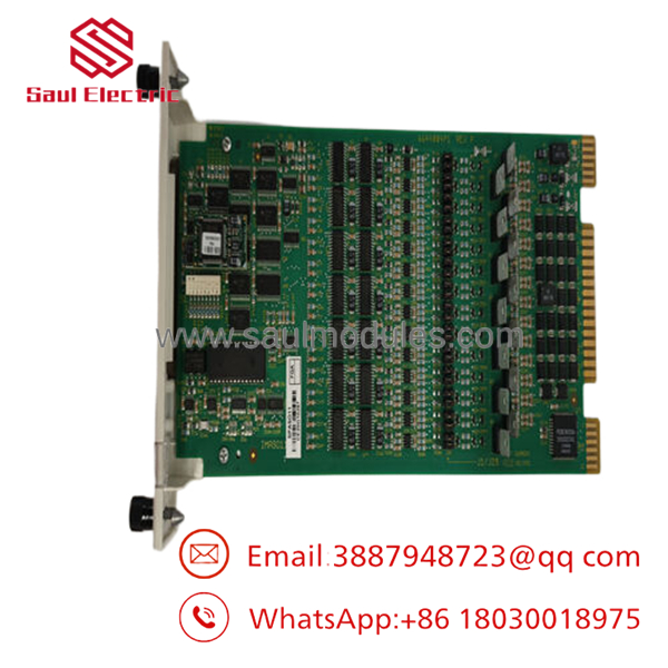
- SPASO11
Installation & Configuration Guide
Stage 1: Pre-Installation (Prep & Safety)
- Verify the target rack slot assignment inside the Bailey mounting unit (MMU) chassis.
- Put on a grounded ESD wrist strap and clamp its reference clip to the copper cabinet grounding bar.
- Check the physical dip switch arrays and jumper headers on the component layout to ensure they precisely match the field channel configuration of the card being replaced.
Stage 2: Removal
- Unlatch the upper and lower plastic module retaining clips on the faceplate of the card assembly.
- Carefully pull the card straight forward out of the chassis guide rails, using steady, slow pressure to avoid snagging any external ribbon lines.
- Place the removed board directly into an ESD-protective shielding bag.
Stage 3: Installation (Clone & Seat)
- Configure all onboard hardware jumpers on the new surplus SPASO11 to mirror the settings of the original board exactly (matching input types like Pt100 vs. Type K).
- Align the top and bottom circuit edges with the plastic tracks of the MMU chassis slot.
- Push the module smoothly backward until the rear card-edge gold contacts seat completely into the backplane connector socket, then lock the faceplate retaining clips.
Stage 4: Power-On & Testing
- The backplane automatically powers the slave module upon connection. Observe the local faceplate status indicators.
- Check your central engineering workstation console to ensure the master controller establishes a clean handshake with the new slot address without throwing configuration mismatch alarms.
- Run an online input channel calibration check to verify that the field temperature readings on your HMI screens align with physical process parameters.
Firmware/Software Versions & Upgrade Notes
The operates as an execution-level analog slave module managed by a primary controller board. It relies on internal firmware held in onboard ROM chips to handle its basic analog-to-digital conversion and slave-bus communications.
When setting up this new surplus item, ensure that your master controller’s block configuration matches the revision suffix of the replacement hardware. If your master controller uses older system firmware (pre-revision 3.0), you may need to re-verify the input definition blocks within your engineering software tool. This ensures the system scales the 15-channel analog data mapping correctly without introducing addressing errors across the internal slave network.
Frequently Asked Questions (FAQ)
Is this analog input board brand new, or has it been pulled from a dismantled system?
This board is a guaranteed New Surplus component. It has never been deployed in an active field cabinet, run in a production line, or subjected to electrical repair. Every unit is kept in temperature-controlled storage and opened exclusively for our warehouse quality check and inbound inspection. We do not sell used or refurbished hardware.
Why should we spend more on a New Surplus module when cheap refurbished options are available online?
Refurbished analog boards carry high operational risks because their input multiplexers and isolation circuits age under high thermal stress and degrade silently over time. A failure or drift on an old input card can distort temperature data, leading to false safety trips or missed overheating events on high-value equipment. Sourcing a new surplus component completely eliminates this risk, providing a fresh 10–15 year operational life and protecting your plant from expensive unplanned downtime.
Do I need to buy special programming tools to configure the input channels on this card?
No separate software programming tool is required for the card itself. The board’s basic channel behaviors are set via physical onboard jumpers and hardware DIP switches. Once these match the old card’s configuration, the master controller manages the remaining engineering block assignments automatically.
Can the module be hot-swapped while the Bailey rack is powered?
Yes. The Bailey Infi 90 and Harmony backplane architectures support the safe extraction and insertion of slave modules while the system is powered. However, ensure you are wearing a properly grounded ESD wrist strap during the swap to prevent static shocks from damaging adjacent active slots.
What kind of warranty coverage applies to this hardware component?
We provide a comprehensive 1-year warranty on this New Surplus module, starting from the day it leaves our shipping center. This policy matches original OEM warranty parameters, providing dependable safety and security for your spare parts inventory.

 Start Chat


