





Description
Key Technical Specifications
| Parameter | Value / Specification |
| Part Number | SPIIT13 |
| Module Type | Digital/Discrete Output (DO) |
| Number of Channels | 16 fully isolated channels |
| Output Type | Solid-state Triac (AC switching) |
| Operating Voltage Range | 24 V AC to 140 V AC (47 to 63 Hz) |
| Maximum Load Current | 2.0 A per channel max (subject to rack thermal limits) |
| Off-State Leakage Current | Less than 2.0 mA at 120 V AC |
| Isolation Voltage | 1,500 V RMS continuous channel-to-channel and channel-to-logic |
| Onboard Intelligence | Microprocessor-based diagnostic execution, open-circuit, and short-circuit detection |
| Power Consumption | 3.5 W nominal from backplane |
Product Introduction
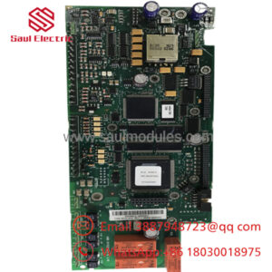
The ABB SPIIT13 is a high-density, intelligent isolated Triac output module designed for installation within Symphony Plus and legacy Infi 90 Distributed Control System (DCS) Harmony Racks. Equipped with 16 independent solid-state Triac channels, this module is engineered specifically for switching alternating current (AC) field loads such as solenoids, motor starters, control relays, and indicator panels. The onboard microprocessor adds an advanced diagnostic layer, monitoring loop integrity and device health in real time.
Automation professionals select the SPIIT13 for applications demanding fast switching cycles and high reliability under heavy electrical stress. Unlike standard relay cards that suffer from mechanical contact wear over time, the solid-state Triac architecture ensures millions of silent, wear-free operations. Furthermore, the 1,500 V RMS isolation boundary prevents severe field-side voltage transients, inductive spikes, and cross-channel electrical noise from breaching the sensitive backplane control logic.
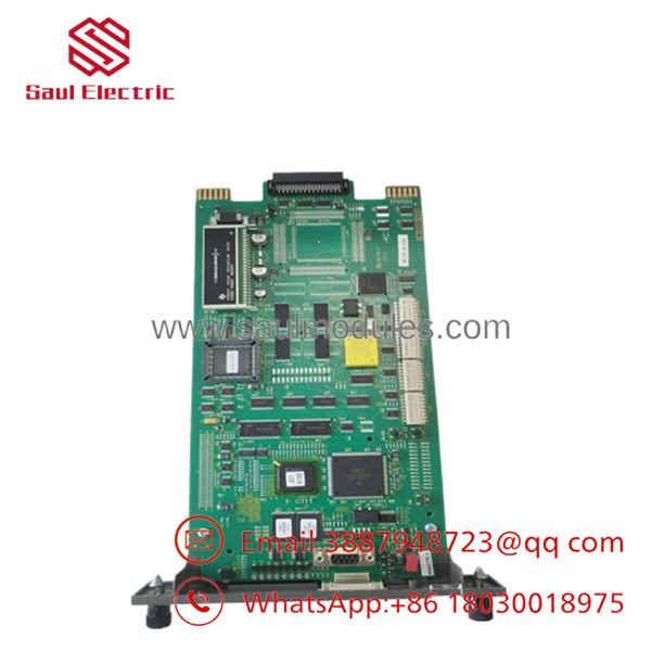
- SPIIT13
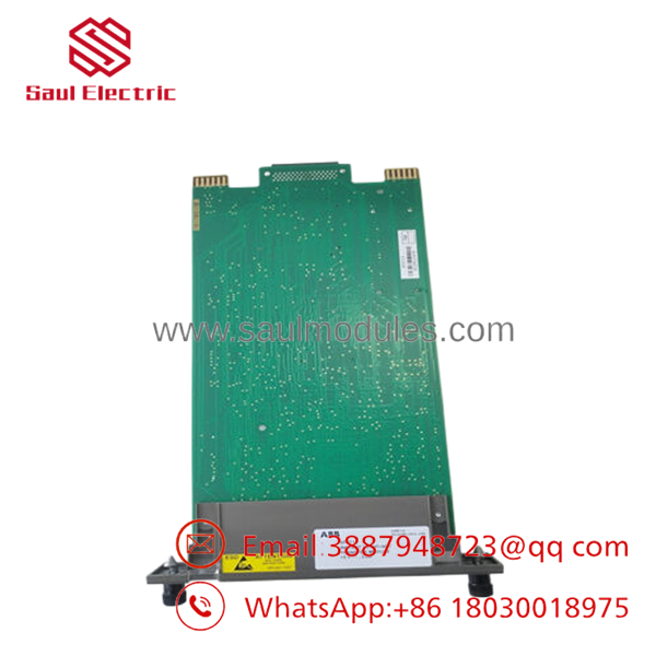
- SPIIT13
Installation & Configuration Guide
Stage 1: Pre-Installation Preparation (Estimated Time: 10 minutes)
- ⚠️ Safety First: Isolate and turn off all external AC field power sources (24 V–140 V AC) feeding the targeted termination unit. Failing to de-energize the field wiring poses a severe shock hazard and risks shorting out the module pins during handling.
- Tools Required: Grounded anti-static (ESD) wrist strap, fine-tip flat screwdriver, digital multimeter, smartphone (for physical configuration reference).
- Data Backup: Check that your engineering workstation has saved a current backup of the active configuration template. Document the physical position of the hardware dip switches (Module Address) located on the card body before sliding it out.
Stage 2: Removing the Old Module (Estimated Time: 5 minutes)
- Fasten your grounded ESD wrist strap securely to the cabinet frame grounding point.
- Locate the failed SPIIT13 card in the rack layout.
- Unlatch the upper and lower plastic locking tabs mounted on the module’s front faceplate.
- Pull the module straight forward along the card guide rails. Ensure you do not pull at an angle to avoid damaging the multi-pin backplane connector. 5. Place the pulled card directly into an ESD-safe protective shielding bag.
Stage 3: Installing the New Module (Estimated Time: 10 minutes)
- Extract the new module from its anti-static packaging while staying grounded.
- Configuration Clone (Crucial): Find the onboard hardware dip switch blocks (typically labeled for Module Address and diagnostic modes). Adjust the toggle switches on the new module to mirror the old card’s configuration exactly. If the address is incorrect, the master controller will fail to map the I/O points.
- Align the upper and lower edges of the PCB with the plastic guides inside the empty slot channel.
- Carefully slide the board into the slot until it mates completely with the backplane connector. Press firmly until the faceplate latches click shut.
📋 Self-Checklist:
- [ ] Module hardware address dip switches are identical to the original card settings.
- [ ] Board is fully seated and securely locked into the Harmony backplane.
- [ ] Field-side AC distribution fuses are checked and intact.
Stage 4: Power-On & Testing (Estimated Time: 15 minutes)
- Slide the card into the live rack; backplane power initializes immediately.
- Observe the front panel LEDs. The status light should stabilize to a steady green. A solid red light implies an internal self-test failure or an addressing conflict.
- Turn back on the external AC power lines supplying the field loads.
- Force a test channel output via Composer or S+ Engineering software. Verify that the matching field load activates, and confirm that the onboard diagnostic LEDs mirror the software command.
- ⚠️ Troubleshooting Note: Because Triacs require a minimum holding current to stay latched, very small field loads (like low-draw LED pilot lights) may flicker or fail to turn off due to off-state leakage current. If a channel refuses to turn off, check that the load draws at least 50 mA or wire a parallel load resistor.
Frequently Asked Questions (FAQ)
Can the handle direct current (DC) field loads?
No, it cannot. The utilizes solid-state Triac components, which inherently rely on the zero-crossing nature of alternating current (AC) to open and close the circuit properly. If you connect a DC voltage source to a Triac output, once the channel is activated, it will remain latched on permanently until you completely disconnect the physical wire or kill the main power feed. For DC loads, use a transistor or dry-contact relay module instead.
What does the “Intelligent” designation actually mean for this module?
Unlike basic digital output boards that blindly push a voltage signal, the features a dedicated onboard microprocessor. This processor performs continuous background diagnostics on the health of each loop. It can detect open-circuit conditions (such as a broken field wire or burned solenoid coil) and short-circuit faults, passing these granular error status flags back to the master controller to trigger alarm graphics on the operator’s HMI.
Can I hot-swap this module under power while the rest of the rack is running?
Yes. The Harmony Rack architecture supports the hot-swapping of peripheral I/O modules like the . You can pull a faulty board and insert a new one without shutting down adjacent control modules or taking the main node controller offline. However, pulling the module will instantly drop all 16 AC output channels, so ensure that any interlocked pumps, valves, or starters are placed in a safe manual configuration prior to extraction.
Why do I see a small voltage on the output channel even when it is turned off?
This is a standard characteristic of solid-state Triac switches. To protect the internal components from rapid voltage rises (dv/dt), Triacs utilize internal RC snubber networks. These snubbers allow a tiny amount of off-state leakage current (typically under 2.0 mA) to pass through the terminal even when deactivated. If you connect an extremely high-impedance device, your multimeter will read a floating ghost voltage.
Does the require separate external fuses for each channel?
While the module features high isolation barriers to protect the control rack logic, it does not possess individual, onboard user-replaceable branch fuses for the high-current field paths. It is highly recommended to use a fused field termination unit (such as a fused NTDI component) or external terminal block fuses rated for your specific load profile to protect the individual Triac channels from direct field short circuits.


 Start Chat


