





Description
Key Technical Specifications
| Parameter | Value |
|---|---|
| Manufacturer | ABB |
| Model Designation | TU811V1 / TU811 |
| Product ID | 3BSE013231R1 |
| MTU Type | Compact profile, shrouded field wire termination base |
| Supported Modules | Various S800 I/O modules (e.g., DI811, DI814, DO814, AI811) |
| Terminal Configurations | 2 vertical rows of 8 shrouded screw-clamp compression terminals (16 points total) |
| Max Voltage Isolation | 250 V continuous (suitable for 120/230 V AC or high-voltage DC signaling) |
| Max Current per Terminal | 3 A |
| Wire Gauge Range | 0.2 to 2.5 mm² (24 to 14 AWG) |
| Backplane Interconnect | Integrated internal ModuleBus pass-through connectors |
| Mechanical Security | Customizable positioning keys to prevent inserting incorrect module types |
| Mounting Style | Horizontal or vertical standard 35 mm DIN Rail |
| Environmental Safety | Class I Div 2 cULus, ATEX Zone 2, G3 harsh environment rating |
| Dimensions & Weight | 58 mm W × 170 mm H × 51 mm D |
Product Introduction & Supply Chain Strategy
The ABB TU811V1 (3BSE013231R1) is a compact module termination unit (MTU) designed to mount and interface high-voltage S800 I/O modules within the System 800xA automation framework. Unlike its low-voltage counterpart (the TU810V1), the TU811V1 features a specialized, shrouded 16-point terminal block arrangement capable of safely handling voltages up to 250 V continuous. This makes it the ideal small-footprint selection for landing 120/230 V AC digital inputs or high-voltage control loops directly onto the local ModuleBus backbone without occupying valuable rail width in tight marshaling enclosures.
From an operations and maintenance strategy standpoint, utilizing this baseplate as a New Surplus asset optimizes your Total Cost of Ownership (TCO) while securing necessary grid isolation. Because the MTU is constantly subjected to structural pressure, environmental contamination, and high-voltage arcs during field wiring troubleshooting, its internal tracking paths and terminal components degrade over time. Refurbished alternatives introduce substantial liabilities; micro-fractures in the high-voltage insulation barriers or stripped terminal threads can lead to phase-to-ground short circuits, destroying the entire local ModuleBus rack. Sourcing factory-clean, zero-hour surplus hardware ensures structural compliance and completely isolates your low-voltage processors from unexpected field surges.
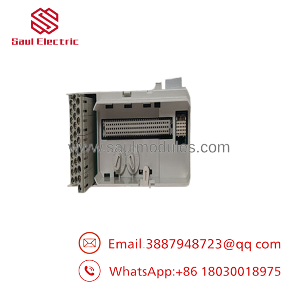
- TU811V1 3BSE013231R1
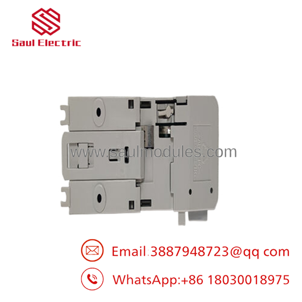
- TU811V1 3BSE013231R1
Installation & Configuration Guide
Stage 1: Pre-Installation (Prep & Safety)
- De-energize the central ModuleBus power supply and verify that all external high-voltage field power lines (120/230 V AC) routed to this slot are locked out and tagged out (LOTO).
- Put on a grounded ESD wrist strap and clamp its reference clip to the copper cabinet grounding bar.
- Configure the mechanical keying pegs on the face of the TU811V1 to match the exact profile of your high-voltage I/O card to prevent accidental cross-insertion of analog boards.
Stage 2: Removal
- Unfasten the 16 shrouded screw terminals, pull the field wiring bundles back carefully, and verify all high-voltage line tags match your panel drawings.
- Disconnect adjacent MTU slots by prying the interlocking side-ModuleBus connectors outward.
- Insert a flathead screwdriver into the lower plastic DIN rail release latch, pry downward, and swing the empty baseplate off the mounting rail.
Stage 3: Installation (Clone & Seat)
- Hook the top mounting groove of the new surplus onto the 35 mm DIN rail, then snap the lower section inward until the rail latch locks tight.
- Slide the module horizontally until its internal ModuleBus contacts mate completely into the adjacent MTU baseplate connector slot.
- Terminate your field wiring back into the 16 shrouded screw slots, torquing each connection firmly to prevent high-resistance joints that generate localized heat.
Stage 4: Power-On & Testing
- Before plugging the electronic S800 I/O module onto the new baseplate, use a digital multimeter to check the terminal points and verify that field voltages match expected levels.
- Align the target high-voltage I/O module with the baseplate guide pins and slide it straight home until its plastic side latches lock into the frame.
- Reapply primary control power and field power. Verify the module runs its startup sequence smoothly and that your central engineering workstation shows clear, error-free communication with the slot node.
Firmware/Software Versions & Upgrade Notes
The is a passive mechanical and electrical routing baseplate asset. It does not feature an onboard microprocessor, programmable flash memory blocks, or updateable firmware code. It functions independently of the software version driving your master AC 800M controller or field communication interfaces (such as the CI801 or CI840).
However, you must ensure that your Control Builder configuration matches the specific I/O module variants mounted to the baseplate. If your engineering software configuration expects a specific module variant (e.g., an AI811) but the physical mechanical keying on the blocks it from seating, the system will trigger a persistent hardware mismatch alarm. Always document your physical mechanical key positions during field upgrades to prevent configuration errors.
Frequently Asked Questions (FAQ)
Is this baseplate brand new or an item salvaged from an old panel?
This module is a guaranteed New Surplus item. It has never been installed in a working field panel, wired into an active system, or subjected to industrial warehouse pollution. It is clean inventory preserved in controlled storage conditions and opened only for our inbound quality check. We maintain a zero-tolerance policy for refurbished components.
What is the primary difference between the and the look-alike TU810V1 baseplate?
The primary difference is the voltage rating and terminal configuration. The TU810V1 is rated for low-voltage applications up to 50 V max (ideal for 24 V DC lines). The features deeply shrouded terminal wells and enhanced insulation barriers, allowing it to safely handle up to 250 V continuous, making it suitable for 120 V AC or 230 V AC digital utility circuits.
What is the exact function of the small plastic wheels/pegs on the baseplate face?
These are mechanical coding keys. They are configured to establish a unique mechanical profile that matches only one specific type of S800 I/O card. This safety mechanism ensures that if a technician tries to plug an incompatible card into the slot during an emergency swap, the module will be physically blocked from seating, preventing electrical damage.
Can I run standard 4-20 mA analog loops through this baseplate?
While the baseplate can physically route low-voltage signals, it is specifically designed and mechanically keyed for high-voltage I/O cards (such as the DI811 120V input card). If your application requires 4-20 mA analog inputs, the TU810V1 or TP830 baseplates are the appropriate, standard selections.
What type of warranty protection covers this hardware component?
We provide a comprehensive 1-year warranty on this New Surplus module termination unit, starting from the day it leaves our warehouse. This matches standard OEM protection parameters, giving your maintenance team complete peace of mind.

 Start Chat


