





Description
Key Technical Specifications
| Parameter | Value |
|---|---|
| Manufacturer | ABB |
| Model Designation | TU890 |
| Product ID | 3BSE013232R1 |
| MTU Type | Compact profile, intrinsically safe field wire termination base |
| Supported Modules | Intrinsically Safe S800 I/O modules (e.g., DI890, DO890, AI890, AO890) |
| Terminal Configurations | 2 vertical rows of 8 blue screw-clamp compression terminals (16 points total) |
| Application Environment | For interfacing instruments located in Zone 1 / Zone 0 / Class I Div 1 areas |
| Isolation Architecture | Segregated routing paths separating intrinsically safe field wiring from non-IS backplane logic |
| Wire Gauge Range | 0.2 to 2.5 mm² (24 to 14 AWG) |
| Backplane Interconnect | Integrated internal ModuleBus pass-through connectors |
| Mechanical Security | Customizable positioning keys to prevent inserting incorrect module types |
| Mounting Style | Horizontal or vertical standard 35 mm DIN Rail |
| Environmental Safety | ATEX, IECEx, cULus Hazardous Locations certified, G3 harsh environment rating |
| Dimensions & Weight | 58 mm W × 170 mm H × 51 mm D |
Product Introduction & Supply Chain Strategy
The ABB TU890 (3BSE013232R1) is a specialized compact module termination unit (MTU) engineered specifically to host and interface intrinsically safe (IS) S800 I/O modules within the System 800xA control framework. Distinctively housed with bright blue terminal blocks to denote hazardous area wiring compliance, the TU890 acts as a secure firewall. It ensures strict physical separation and galvanic isolation between the low-voltage microprocessor circuits running on the electrical ModuleBus backplane and field instrument loops extending into explosive atmospheres (Zone 1, Zone 0, or Class I, Division 1).
From a risk-mitigation and compliance standpoint, procurement of this unit as a New Surplus asset directly secures your facility’s safety ratings while optimizing the Total Cost of Ownership (TCO). Because the TU890 functions as a certified explosion-protection safety barrier, its internal isolation distances, potting layers, and terminal shielding boundaries are strictly bound to regulatory tolerances. Sourcing a refurbished or used alternative introduces unacceptable safety and legal liabilities; microscopic cracks in the internal insulation layers or environmental breakdown can allow a voltage fault to bridge directly into a hazardous gas environment. Sourcing factory-clean, zero-hour surplus hardware guarantees pristine dielectric breakdown safety and eliminates the threat of regulatory shutdown or plant accidents.
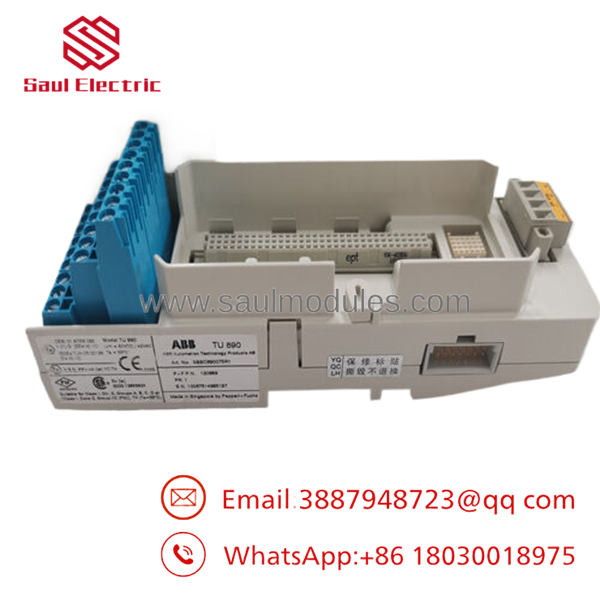
- TU890
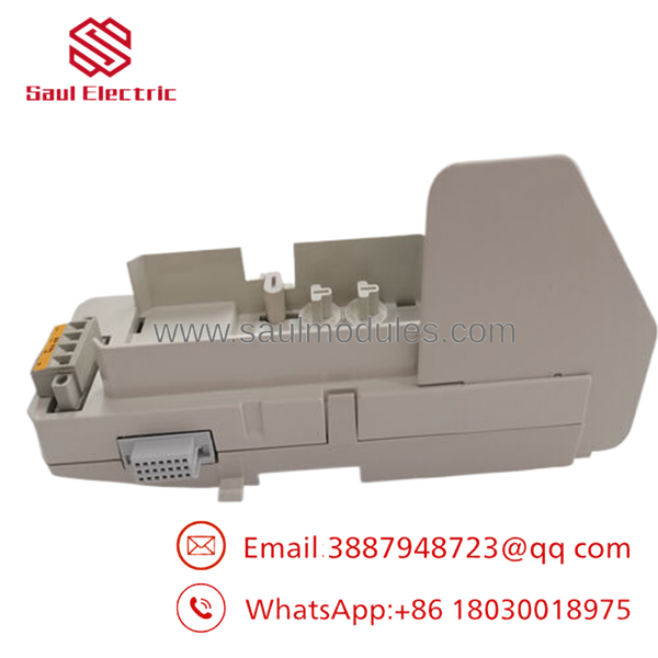
- TU890
Installation & Configuration Guide
Stage 1: Pre-Installation (Prep & Safety)
- Verify the entire field cabinet section is isolated and that all active loops heading to the hazardous field boundary are locked out and tagged out (LOTO).
- Put on a grounded ESD wrist strap and connect its reference lead directly to the main copper grounding strip of the cabinet framework.
- Configure the mechanical keying wheels on the face of the to match the exact profile of the specific intrinsically safe I/O module type (e.g., AI890) slated for this slot.
Stage 2: Removal
- Unfasten the 16 blue screw terminals and move the hazardous area field wiring bundles back carefully, ensuring all safety tags remain fully intact.
- Disconnect the adjacent MTU modules by sliding the side-locking ModuleBus connectors outward.
- Insert a flathead screwdriver into the lower plastic DIN rail release latch, pry it downward, and lift the empty baseplate off the mounting rail.
Stage 3: Installation (Clone & Seat)
- Snap the new surplus onto the 35 mm DIN rail, checking that the internal grounding spring seats tightly against the metal rail profile.
- Slide the unit horizontally to mate its internal ModuleBus contacts completely into the adjacent MTU baseplate connector slot.
- Terminate your intrinsically safe field wiring into the blue terminal positions, keeping wire dressing dressed cleanly away from any neighboring non-intrinsically safe power lines.
Stage 4: Power-On & Testing
- Before plugging the electronic S800 I/O module onto the baseplate, use a digital multimeter to check the terminal points and verify that no unauthorized voltages are bleeding onto the IS terminals.
- Align the target intrinsically safe I/O module with the baseplate guide pins and slide it straight home until its plastic side latches lock into the frame.
- Reapply primary control power. Verify the module runs its startup sequence smoothly and that your central engineering workstation shows clear, error-free communication with the slot node.
Firmware/Software Versions & Upgrade Notes
The is a passive mechanical and electrical routing baseplate asset. It does not contain an internal microprocessor, programmable flash memory blocks, or updateable firmware code. It functions independently of the software version driving your master AC 800M controller or field communication interfaces (such as the CI801 or CI840).
However, you must ensure that your Control Builder configuration matches the specific I/O module variants mounted to the baseplate. If your engineering software configuration expects a specific module variant (e.g., an AI890) but the physical mechanical keying on the blocks it from seating, the system will trigger a persistent hardware mismatch alarm. Always document your physical mechanical key positions during field upgrades to prevent configuration errors.
Frequently Asked Questions (FAQ)
Is this baseplate brand new or an item salvaged from an old panel?
This module is a guaranteed New Surplus item. It has never been installed in a working field panel, wired into an active system, or subjected to industrial warehouse pollution. It is clean inventory preserved in controlled storage conditions and opened only for our inbound quality check. We maintain a zero-tolerance policy for refurbished components.
Why does a new surplus cost significantly more than a standard refurbished unit?
Intrinsically safe baseplates are certified safety barriers that prevent explosions in gas-filled or dust-filled zones. Refurbished units frequently suffer from invisible damage, such as localized insulation degradation, tracking paths caused by chemical vapor deposition, or tiny cracks in the printed circuit board traces. A failure in an old safety baseplate can permit high voltages to escape into hazardous areas, posing severe fire and explosion risks. Purchasing new surplus hardware completely eliminates this hazard, providing factory-certified insulation performance.
Why are the terminals on the TU838/TU810 modules grey, while the terminals on the are bright blue?
The bright blue housing on the is an industry-wide regulatory color standard designating Intrinsic Safety (IS) connections. This allows maintenance technicians to instantly see which wiring harnesses carry restricted energy into hazardous process zones, ensuring non-IS wires are never accidentally mixed or tied into the same tracking paths during field maintenance.
Can I mix intrinsically safe modules on the same DIN rail with standard TU810 baseplates?
Yes, the ModuleBus backbone allows physical interconnection between standard and intrinsically safe MTU bases. However, you must install an approved physical barrier or partition plates (such as the ABB TU807 spacing block) between standard blocks and the blue IS blocks to maintain the required safety separation distance dictated by ATEX/IECEx standards.
What type of warranty protection covers this hardware component?
We provide a comprehensive 1-year warranty on this New Surplus module termination unit, starting from the day it leaves our warehouse. This matches standard OEM protection parameters, giving your maintenance team complete peace of mind.


 Start Chat


