





Description
Key Technical Specifications
| Parameter | Value |
| Manufacturer | ABB |
| Part Number (Model) | UAC389AE02 |
| Catalog Number (PNC) | HIEE300888R0002 |
| System Application | UNITROL 5000, UNITROL 6000, MEGATROL |
| Input Voltage | 24 VDC (±10% operational tolerance) |
| Power Consumption | Approximately 15 W internal board draw |
| Communication Interfaces | High-speed fiber optic channels, proprietary ABB system bus |
| Processor Type | High-performance DSP / FPGA architecture |
| Operating Temperature | 0 to +55 °C |
| Storage Temperature | −40 to +70 °C |
| Humidity Constraints | 5% to 95% non-condensing relative humidity |
| Weight | 0.85 kg (board only, excluding packaging) |
| Dimensions | Standard ABB processing module form factor |
Product Introduction
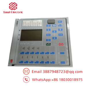
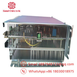
The ABB UAC389AE02 HIEE300888R0002 is a high-performance control and processor board engineered for large-scale synchronous generator excitation systems, primarily within the UNITROL 5000 and early UNITROL 6000 hardware topologies. Operating as a core arithmetic and interface hub, this module processes complex regulation algorithms required to maintain generator voltage stability, control reactive power flow, and manage transient grid conditions in utility-scale power plants and heavy industrial co-generation facilities.
Plant engineers select this specific board variant because it provides hardware-level timing accuracy for thyristor firing pulse generation and high-speed analog loop execution. Unlike universal control components, the hardware architecture is hardened against severe electromagnetic interference (EMI) typical of high-current excitation cubicles, eliminating signal drift and preventing unexpected turbine trips caused by control loop dropouts.
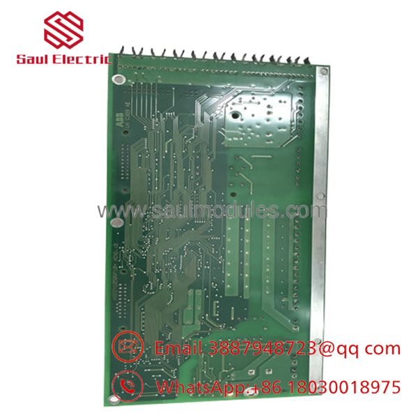
- UAC389AE02 HIEE300888R0002
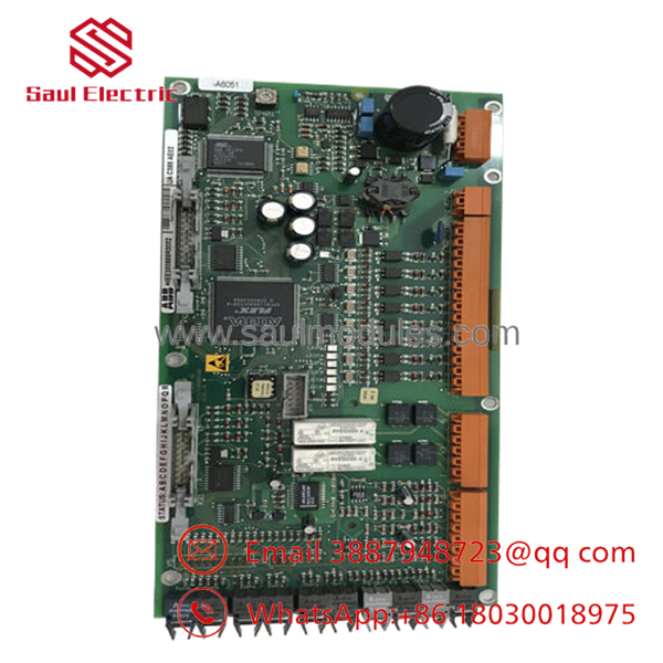
- UAC389AE02 HIEE300888R0002
Installation & Configuration Guide
Stage 1: Pre-Installation Preparation (Estimated Time: 15 Minutes)
- ⚠️ Safety First: Excitation cubicles house lethal voltage and current levels. Coordinate with operations to de-energize the generator excitation transformer. Lock out and tag out (LOTO) the main AC input breakers and the 24 VDC control power supplies. Wait at least 10 minutes to allow the field discharge resistors to dissipate any residual energy stored in the rotor field windings and DC-link capacitors. Verify zero voltage on the bus using a calibrated multimeter.
- Tools Required: Grounded ESD wrist strap, anti-static mat, standard PH1 and PH2 insulated screwdrivers, fiber-optic cleaning kit, smartphone or tablet for hardware state recording.
- Data Backup: Connect your engineering laptop via the local service port. Upload and export the current parameter tuning files, firmware application image, and fault logger data from the active system controller. Document local node addresses, MAC addresses, and specific physical jumper positionings on the chassis.
Stage 2: Removing the Old Module (Estimated Time: 10 Minutes)
- Attach your ESD wrist strap to a verified frame ground point.
- Disconnect the low-voltage auxiliary power plugs.
- Carefully unlatch and pull out the fiber-optic cables. Avoid bending them past a 30 mm radius. Immediately apply protective dust caps to the fiber ends and the board ports.
- Back out the retaining screws securing the board into the subrack assembly.
- Grasp the module firmly by the faceplate ejector handles, unlock them simultaneously, and slide the board straight out along its guide rails to prevent twisting and damaging the rear backplane pin connections.
- ⚠️ Note: Do not discard or ship the old board back immediately. Keep it on an ESD mat nearby to physically cross-reference hardware revisions, EEPROM chips, or physical jumper settings during the swap.
Stage 3: Installing the New Module (Estimated Time: 15 Minutes)
- Maintain strict ESD grounding. Extract the new UAC389AE02 board from its anti-static shielding bag.
- Configuration Clone (Crucial): Inspect the physical board surface. Check for any manual configuration blocks, DIP switches, or hardware jumpers. Ensure they exactly mirror the layout of the old board you just removed. A wrong jumper setting here can cause a boot failure or prevent the board from recognizing the high-speed system bus.
- Clean the fiber-optic cable tips using an isopropyl alcohol wipe or specialized fiber click-cleaner before insertion.
- Align the board with the rack slots and slide it smoothly inward until the rear DIN connectors sit firmly against the backplane. Lock the ejector handles down.
- Hand-tighten the faceplate retaining screws to ensure continuous chassis grounding. Reattach the fiber-optic links and electrical terminal plugs.
- Self-Checklist:
- [ ] Hardware jumpers/switches match old board layout exactly.
- [ ] All fiber-optic connections clicked securely into place.
- [ ] Faceplate grounding screws are tight and secure.
Stage 4: Power-On & Testing (Estimated Time: 20 Minutes)
- Pre-Power Check: Measure resistance across the 24 VDC input terminals to verify there are no direct dead shorts on the board power rail.
- Power-On Steps:
- Energize the 24 VDC control power supply line only; do not close the main thyristor bridge AC supply yet.
- Watch the faceplate diagnostic LEDs during the boot sequence. The system should complete its initialization within 30 seconds. A steady Green status indicates normal operation, while a flashing or solid Red error light implies a configuration or firmware mismatch fault.
- Establish an engineering link via your terminal software. Query the hardware register to confirm that the board is using the correct system firmware version. If the revision differs from your plant standard, flash the saved firmware image to this new board.
- Reload the backed-up parameter configuration files and perform a cold reboot of the controller to commit the memory changes.
- Conduct a dry-run I/O loop check, validating loop continuity back to the firing pulse units before returning the generator to live service.
- ⚠️ Troubleshooting Note: If the system bus generates a “Link Loss” error immediately after boot, power down and check for a microscopic spec of dust inside the fiber-optic receiver barrel, or verify that the RX and TX fiber lines were not accidentally swapped during installation.
Frequently Asked Questions (FAQ)
Can I hot-swap the UAC389AE02 board while the generator is running?
Absolutely not. This is a critical processor board that calculates active regulation loops and manages firing commands for the thyristor bridges. Pulling this board while the system is under load will instantly break the control loop, causing a high-energy field loss condition, an immediate turbine-generator trip, and potential damage to the rotor windings. Always power down the entire control rack before attempting a replacement.
Is this board genuinely new, considering that the series is mature?
Yes. Our inventory consists of New Original / New Surplus stock. These units are sourced from canceled construction projects, plant modernization reserves, or strategic spare-parts allocations. They have never been placed into active service or exposed to thermal cycles in an active control panel. Every board is maintained in climate-controlled storage inside ESD packaging.
What happens if the firmware on this replacement board doesn’t match my active system?
If the firmware version running on the new is incompatible with your existing master controller firmware, the system will trigger a communication initialization error or a configuration mismatch trip. You must use the ABB specialized maintenance tool to verify the revision level upon first boot. If a discrepancy exists, download your site-validated firmware image onto the new board before attempting to execute control logic.
Why is your pricing lower than the standard OEM factory list price?
Because we source directly from surplus market assets, warehouse liquidations, and overstock inventories rather than through the traditional OEM factory production queue. This enables us to pass wholesale asset savings directly down to your procurement team without compromising component authenticity or reliability.
What kind of warranty coverage comes with this module?
Every single board we ship comes standard with a 1-year replacement warranty. If the module experiences any component-level failure under normal operating parameters within 12 months of delivery, we will replace the unit or issue a refund if stock is limited.
Core Strategy 1: SOP Quality Transparency
To ensure industrial reliability and give you complete peace of mind when ordering surplus critical infrastructure components, every board passes through a multi-stage Quality Control protocol before shipment:
- Inbound Inspection & Traceability:
- Source verification is performed by matching component batch codes against trusted industrial procurement manifests.
- Anti-counterfeit analysis confirms original PCB solder masking, laser-etched silkscreen markings, and unique ABB serial number profiles.
- A high-resolution visual inspection checks for component aging, micro-fissures, physical terminal wear, or past rework signs.
- Electrical Parameter Testing:
- Isolation resistance is evaluated using a Fluke 1507 insulation tester at 500 VDC between the power rails and the chassis frame to guarantee a value >10 MΩ.
- Ground trace continuity across the entire circuit matrix is confirmed to verify optimal noise dissipation paths.
- Live Functional Testing:
- The board is populated onto a genuine ABB test subrack powered by a clean, stable 24 VDC power supply.
- We run a standard power-on self-test (POST) to monitor the boot sequence and individual diagnostic status indicators.
- All fiber-optic communication ports are run through a loopback ping test to verify that data transmission rates meet OEM specifications without packet loss.
- The system runs continuously under test-bench load configurations for over 24 hours while being monitored with an infrared thermal camera to check for any component hotspots.
- An official QC Test Report is generated for your internal maintenance logs. Live test videos or photos of your specific serial number on our bench are available by request.
- Firmware & Configuration Verification:
- The current internal firmware build is read out and documented.
- Default jumper selections are audited against factory specifications to provide a known baseline.
- Final QC & Secure Packaging:
- The lead inspector signs off on the quality sheet after checking the serial numbers one last time.
- The module is wrapped in a heavy-duty, static-shielding ESD bag.
- We cushion the board using dense, shock-absorbent bubble wrap inside a thick, multi-wall corrugated cardboard box to survive demanding international shipping routes.
- A tamper-evident “QC Passed” seal is applied to the final box with the inspection date.
Core Strategy 2: Technical Pitfall & Survival Guide
Replacing an excitation control card carries a high risk of extended downtime if small details are overlooked. Keep these 5 real-world field traps in mind:
- ❗ Firmware Revision Drifts:
- The Trap: Swapping in a board with a different firmware suffix often leads to a “Chassis Comm Fail” or missing register maps when communicating with the master controller.
- Survival Strategy: Never assume a new surplus board is pre-flashed to your plant’s specific patch level. Check the label, check the software registry on the old unit before removal, and make sure your engineering laptop has the correct software packages ready to perform an update if required.
- ❗ Overlooking Jumper Settings:
- The Trap: Factory replacement parts are typically shipped with standard default jumper configurations. If your site setup uses specialized node addressing or specific internal terminal terminating resistors, a misaligned jumper can take down the entire internal communications network.
- Survival Strategy: This is a classic 2 AM rookie mistake. Take a high-resolution photograph of the old board’s jumpers right before sliding it out, and double-check that your replacement unit mirrors those positions pin-for-pin before it goes into the rack.
- ❗ Fiber Optic Cable Contamination:
- The Trap: Even a microscopic speck of airborne dust or fingerprint grease on a fiber optic connector tip can attenuate the light signal enough to cause intermittent network drops, resulting in a spurious system trip once the generator is loaded.
- Survival Strategy: Keep dust caps on all fiber links until the exact moment they are plugged in. Always wipe down cable tips using dedicated optical cleaning tools—never blow on the connectors or wipe them with a standard shirt sleeve.
- ❗ Backplane Connector Physical Strain:
- The Trap: Forcing a module into a misaligned or warped subrack can bend or break the high-density pins on the backplane connector, causing permanent damage to the expensive chassis frame.
- Survival Strategy: If the card doesn’t slide into the rack smoothly, do not force it. Pull it back out, check for obstructions along the guide rails, inspect the backplane pins with a flashlight, realign the module, and try sliding it in again.
- ❗ Inadequate Static Control:
- The Trap: Modern DSP and FPGA chips are highly susceptible to latent Electrostatic Discharge (ESD) damage. Handling a raw board without an grounding strap in a dry, winter climate can degrade internal gates without immediate failure, causing the board to fail unexpectedly months down the line.
- Survival Strategy: Treat every card with care. Never touch the raw surface traces or connector contacts directly. Work on a grounded mat and always wear a tethered wrist strap during installation.

 Start Chat


