





Description
Key Technical Specifications
| Parameter | Value / Specification |
| Part Number | UFC719AE01 / 3BHB003041R0101 / 3BHB000272R0001 |
| Module Classification | IOEC Universal Field Controller Board |
| Input Supply Voltage | 24 V DC (Nominal range: 20 V to 30 V DC) |
| I/O Capacity | Supports up to 32 Digital I/O channels and 8 high-precision Analog channels |
| Communication Layer | Modbus RTU/TCP, CANopen, Masterbus 300 network matching |
| A/D Processing Error Rate | Less than 0.1% full scale |
| Isolation and Protection | Heavy industrial EMC certified, electrostatic discharge resistance >15 kV |
| Mounting Architecture | Direct chassis rack mount / drive interface cradle |
| Operating Temperature | −20 to +60 °C (Component rating extensions up to 85 °C) |
| Weight | 1.18 kg |
Product Introduction
The ABB UFC719AE01 is a critical, high-reliability IOEC universal field controller and I/O interface board engineered for ABB’s high-power converter platforms, large-scale excitation equipment (such as MEGATROL packages), and legacy Advant Master/AC 800M integration environments. The board functions as a high-speed data acquisition translator, consolidating internal drive telemetry, voltage loops, and binary field safety limits. It bridges these critical signals onto high-level automation buses including Modbus TCP or Masterbus 300 networks.
System architects specify the UFC719AE01 for heavy power electronics installations—such as gas and hydro turbine starter systems or heavy metallurgical rolling mills—where microsecond-level synchronization is mandatory. By isolating system processing logic from aggressive field-side transients, this board handles rapid signal swings without performance degradation. Its multi-protocol serial and Ethernet layout allows it to execute fast local loops independently if upstream supervisor lines experience network delay.
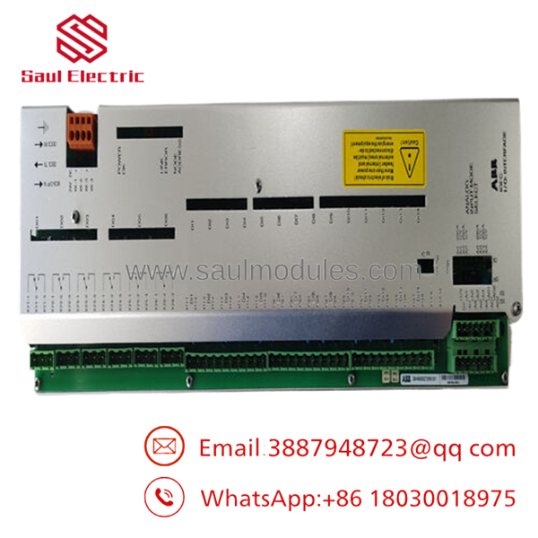
- UFC719AE01

- UFC719AE01
Installation & Configuration Guide
Stage 1: Pre-Installation Preparation (Estimated Time: 15 minutes)
- ⚠️ Safety First: Isolate the drive converter, excitation system, or controller rack from all primary and auxiliary power lines. High-power converter enclosures house lethal residual energy. Lock out and tag out (LOTO) all supplies. Wait a minimum of 10 minutes for the internal capacitive banks to drop below 50 V. Verify a true zero-voltage state with a calibrated high-voltage multimeter across inputs and grounding plates before opening structural card doors.
- Tools Required: Grounded static-elimination (ESD) wrist strap, PH2 cross-head screwdriver, precision instrument screwdriver, multi-meter, fiber-optic cleaning tools (if applicable).
- Data Backup: Ensure you have extracted and saved a full parameters backup file from the connected controller or drive keypad profile (via Control Builder M or DriveWindow toolsets). The UFC719AE01 hosts configuration parameters linked to drive identification blocks; losing synchronization can drop localized system addresses.
Stage 2: Removing the Old Module (Estimated Time: 10 minutes)
- Affix your ESD wrist strap to a verified unpainted metal chassis ground link.
- Label all connected external control wiring arrays, serial sub-plugs, and input/output terminal blocks to prevent line crossing upon reassembly.
- Unplug all internal power cables, ribbon connectors, and terminal lines. Pull straight out on connector housings—never pull or strain the internal copper conductors.
- Loosen the captive retaining fasteners holding the board to its sheet-metal chassis seat.
- Withdraw the board evenly from its alignment tracks to prevent bending any backplane interface pins or hitting surrounding filter boards. Put the card inside an anti-static shield wrap.
Stage 3: Installing the New Module (Estimated Time: 15 minutes)
- Extract the new card from its factory static-shielding package, keeping your personal grounding strap connected.
- Configuration Clone (Crucial): Identify any micro-dip switches, hard-wired selector pins, or jumper options on the circuit layout board. Manually match these jumpers to replicate the old board’s configuration exactly. These jumpers establish network addressing, line signal matching, and master/slave assignments (e.g., configuring the board as IOEC 1 vs. IOEC 2).
- Align the card layout into the chassis guide slots and slide it home until the rear connectors interface completely.
- Fasten the retention screws firmly into the grounding mounting standoffs to ensure a solid, low-impedance path back to the frame enclosure ground.
- Reinstall the signal wire buses and communication lines, locking down any structural retainer clips.
📋 Self-Checklist:
- [ ] Onboard hardware jumpers are set to the identical node ID/address as the original board.
- [ ] Mounting screws are fully secured to maintain proper chassis grounding.
- [ ] Communication plugs are locked down and strain-relief runs are clear of raw edges.
Stage 4: Power-On & Testing (Estimated Time: 20 minutes)
- Apply low-voltage auxiliary power (24 V DC control rail) first, keeping the primary drive/power bridge isolated.
- Check the front-panel or card-edge LED arrays immediately. A healthy module will show a green RUN status. If an ERR or red fault light lights up, turn off the system and verify the jumper configurations and terminal inputs.
- Establish communication through your software workstation (e.g., checking controller hardware trees for active online nodes).
- Safely bring up the primary drive supply lines and perform a cold-loop test of the input and output channels to confirm real-time signal processing is tracking perfectly.
- ⚠️ Troubleshooting Note: If the supervisor system displays a “Module Missing” or “I/O Mismatch” alarm message, the hardware jumpers on the are likely configured to an alternate address group slot. Pull the card and cross-check the configuration settings with the drive system’s engineering manifest.
Frequently Asked Questions (FAQ)
Can the board be hot-swapped while the drive system is actively processing load?
Pulling this card breaks critical telemetry and synchronization loops instantly, which can trigger an un-choppered emergency shutdown or a catastrophic fault within the thyristor or IGBT bridges. Always bring the system to a complete stop and isolate all power feeds before replacing this unit.
Why does this board carry multiple numbers like and 3BHB003041R0101?
This is normal for industrial ABB assemblies. is the functional model classification code, which specifies the hardware platform family and circuit revision profile. The number 3BHB003041R0101 (or 3BHB000272R0001) represents the exact manufacturing part number or stock designation assigned by the factory. Both identifiers must line up to ensure a drop-in replacement that matches your drive software’s expectation.
How does the board handle different signal structures across analog and digital field lines?
The features flexible multi-channel input handling. It includes 8 dedicated high-precision analog channels configured with onboard high-resolution A/D converters to read critical operational data (such as internal voltage scaling and temperature arrays). Concurrently, it maintains up to 32 digital/binary lines configured for high-speed tracking of external breaker logic, trip links, and auxiliary safety interlocking lines.
What should I do if my replacement causes a network error on the Masterbus 300 network?
This issue typically stems from a node address conflict or a baud rate setting error. Check the onboard hardware switches or jumper blocks. If the new card is set to an address that is already occupied by another active node on the loop, communication will crash. Ensure that the new module’s hardware layout mirrors the exact settings of the old unit you removed.
What is the shelf-life behavior of a “New Surplus” board of this complexity?
Because the utilizes solid-state micro-components and robust pulse routing circuitry rather than large electrolytic wet capacitors, its storage shelf life is exceptionally stable. When kept inside a climate-controlled environment within its original anti-static packaging, the board can remain stored for multiple years without degradation. We verify structural status and gate paths before dispatch, ensuring full field reliability supported by a comprehensive 12-month replacement warranty.


 Start Chat


