





Description
Key Technical Specifications
| Parameter | Value / Specification |
| Part Number | UFC760BE42 / 3BHE004573R0042 |
| Platform Compatibility | AC 800PEC (Power Electronics Controller) |
| Processor Type | Combined high-performance RISC processor and real-time FPGA |
| Communication Interface | Onboard high-speed optical fiber channels for distributed I/O connection |
| Input Nominal Supply | 24 V DC (Power derived via standard chassis backplane) |
| Clock Frequency | Multi-gigahertz internal execution loops for microsecond-level gate firing |
| Industrial Standard | Designed for high-power rectification, excitation, and wind/solar inverter control |
| Cooling Requirements | Forced-air via drive cabinet fan assembly |
| Operating Temperature | 0 to +55 °C |
| Weight | 1.45 kg |
Product Introduction
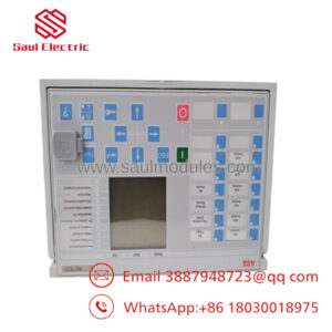
The ABB UFC760BE42 3BHE004573R0042 is a processing core board utilized in the AC 800PEC control system platform. This module combines the fast logic processing of an open industrial controller with the microsecond-range execution speeds required for high-power electronics. By incorporating an onboard FPGA alongside a high-performance embedded processor, it calculates rapid vector algorithms and triggers precise gating commands for high-capacity thyristor and IGBT bridges.
This module is found in specialized, heavy-duty industrial systems, such as static synchronous compensators (STATCOM), gas turbine starters (MEGATROL), large-scale wind turbine converters, and high-voltage direct current (HVDC) systems. The UFC760BE42 relies heavily on its dedicated array of optical fiber ports to communicate with distributed gate drive units and measurement modules. This fiber-optic infrastructure eliminates the risk of electromagnetic noise corruption, ensuring stable system timing even in environments with high electrical interference.
Installation & Configuration Guide
Stage 1: Pre-Installation Preparation (Estimated Time: 15 minutes)
- ⚠️ Safety First: Completely de-energize and isolate the frequency converter, excitation system, or controller rack from all power networks. High-power converter installations hold dangerous residual energy inside their capacitor banks. Lock out and tag out (LOTO) all upstream breakers. Wait at least 15 minutes for the internal voltages to discharge below 50 V. Verify a true zero-voltage state with a calibrated meter before exposing internal boards.
- Tools Required: Grounded ESD wrist strap, Pozidriv PZ2 screwdriver, fiber-optic cleaning tool kit, permanent marker or wire labels, smartphone.
- Data Backup: The UFC760BE42 contains site-specific application code and system configurations within its internal flash memory. Ensure you have a complete, current backup file of your control software (compiled via MATLAB/Simulink or ABB Control Builder M) before removing the existing board to prevent a total loss of parameter settings.
Stage 2: Removing the Old Module (Estimated Time: 10 minutes)
- Fasten your ESD wrist strap and connect its clamp to an unpainted metal portion of the drive chassis ground frame.
- Label each fiber-optic cable and auxiliary wire terminal connected to the front of the UFC760BE42 module. Fiber connections must be plugged back into their exact corresponding transmitter/receiver pairs during reassembly.
- Carefully disconnect the optical cables. Open the retaining latches, pull the connector body straight out, and immediately place protective dust caps onto both the cable tips and the board’s optical transceivers.
- Loosen the captive retaining screws on the top and bottom edge plates of the board.
- Pull the board out along its guide tracks. Keep it flat and steady to avoid damaging components on neighboring slots. Place the unit into a static-shielding bag.
Stage 3: Installing the New Module (Estimated Time: 15 minutes)
- Keep your ESD wrist strap connected while unboxing the replacement UFC760BE42 board.
- Configuration Clone (Crucial): Look for any physical dip switches, rotatory dials, or configuration jumpers on the main PCB body. You must set these switches to mirror the exact settings of the old board. These hardware selections govern node identification, sub-bus speeds, and startup states.
- Slide the board into its slot guides, ensuring the rear card edge aligns smoothly with the backplane connectors. Push firmly until the module is fully seated, then tighten the top and bottom captive retaining screws.
- Clean the optical fiber tips using an industrial fiber cleaning tool. Remove the dust caps and plug each fiber cable back into its corresponding port, making sure they snap firmly into place.
📋 Self-Checklist:
- [ ] All onboard hardware switches match the original module’s configuration.
- [ ] Fiber-optic lines are cleaned and connected to their matching Tx/Rx ports.
- [ ] Top and bottom faceplate screws are tightened to ensure proper grounding.
Stage 4: Power-On & Testing (Estimated Time: 20 minutes)
- Apply 24 V DC auxiliary control power to the rack first, keeping the main high-voltage power lines isolated.
- Monitor the front-panel status LEDs immediately. A normal initialization sequence will show a green RUN light. A flashing or solid red ERR light indicates a self-test issue or an address mismatch.
- Connect your engineering laptop to the module’s diagnostic interface or access the node via the control network.
- Download the backed-up application software and parameter settings to the new module.
- Once the software checks pass, safely apply main power and monitor system telemetry to verify that the control loops and fiber communication lines are operating stably.
- ⚠️ Troubleshooting Note: If the software shows a “Fiber Optic Link Down” or “No Connection” error after installation, verify that the fiber-optic cables are not crossed (Tx plugged into Tx instead of Rx) and ensure the fiber ends were thoroughly cleaned before insertion.
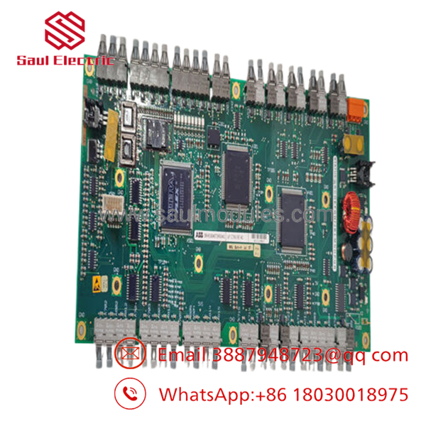
- 3BHE004573R0042
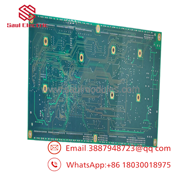
- 3BHE004573R0042
Frequently Asked Questions (FAQ)
Can the board be hot-swapped while the converter is running?
Because this module generates real-time high-speed gating commands and synchronization sequences for power semiconductors, removing the board mid-operation will instantly break the control loop. This will cause an immediate drive shutdown and can lead to severe hardware damage within the thyristor or IGBT bridges due to uncontrolled commutation. Always take the system offline and isolate all power sources before performing a swap.
What is the relationship between model number and part number 3BHE004573R0042?
is the functional model classification code used by engineering teams to identify the module family, hardware structure, and configuration variant. The number 3BHE004573R0042 is the precise factory part number assigned by ABB for logistics, order matching, and manufacturing verification. Both numbers must align to ensure the replacement board matches your existing system hardware and software layout.
Why does this module rely so heavily on fiber-optic links instead of copper wires?
The AC 800PEC series operates in high-power environments where megawatt-level currents switch at high frequencies. This switching creates intense electromagnetic interference (EMI) and radio frequency noise. Traditional copper communication lines would pick up this noise, resulting in corrupted data or timing errors. Fiber-optic cables are immune to electrical noise, allowing the to transfer high-speed gating data and feedback signals over long distances safely and reliably.
Does the new replacement board come pre-loaded with our plant’s operational parameters?
No. Replacement units from factory stock or surplus warehouses are supplied with base operating system firmware, but they contain no application-specific software or parameter profiles. You must use the appropriate engineering toolchain to download your site’s backed-up control program to the new module before it can process inputs or manage the drive system.
What should I check if the module boots up but shows a constant configuration fault?
This issue is typically caused by a mismatch in firmware versions or a misconfigured hardware switch setting. First, confirm that the physical dip switches on the board body match the old module exactly. Second, check that the firmware version running on the new board matches the version expected by your engineering software and upstream controllers. If necessary, flash the module’s firmware to match your site’s standard revision level.


 Start Chat


