





Description
Key Technical Specifications
| Parameter | Value |
| Manufacturer | ABB |
| Part Number (Model) | UFC765AE102 |
| System Compatibility | UNITROL 6000, AC 800PEC Control Systems |
| Input Operating Voltage | 24 VDC nominal via backplane connector |
| Power Consumption | Approximately 25 W peak demand |
| Processor Architecture | High-performance embedded RISC core with integrated FPGA logic |
| Communication Interface | Dedicated high-speed optical links, fast Ethernet maintenance port |
| Operating Temperature | 0 to +55 °C |
| Storage Temperature | −40 to +70 °C |
| Humidity Rating | 5% to 95% non-condensing relative humidity |
| Weight | 1.15 kg (net module weight) |
| Mounting Form Factor | Specialized AC 800PEC subrack slide-in board |
Product Introduction
The ABB UFC765AE102 is a high-reliability, high-speed processing module developed to act as the central computing engine for UNITROL 6000 power excitation systems and industrial-grade AC 800PEC controllers. This card executes the precise, closed-loop arithmetic required to control high-output synchronous machines, dynamically shifting thyristor firing angles to stabilize generator stator voltage and manage reactive power response during major grid variations.
Engineered for critical utilities and industrial co-generation environments, the UFC765AE102 coordinates rapid computational logic with microsecond-level timing accuracy. Its hardware-level isolation protects the digital processor array against intense electromagnetic interference (EMI) and common-mode noise found within high-power rectifier cabinets, eliminating signal distortions that could otherwise lead to unexpected generator trips and costly unplanned downtime.
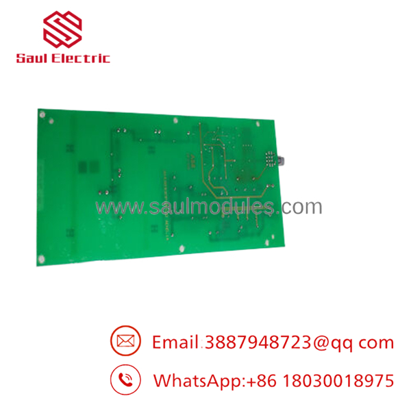
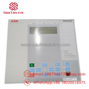
- UFC765AE102
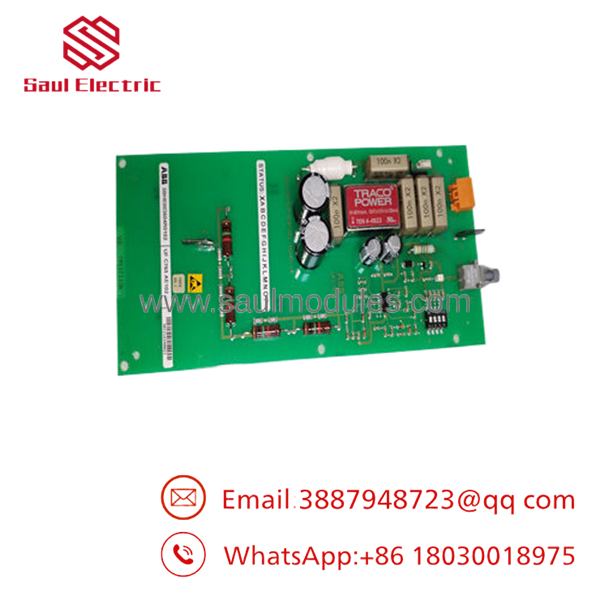
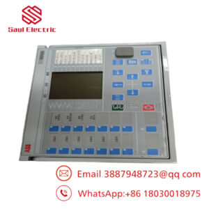
- UFC765AE102
Installation & Configuration Guide
Stage 1: Pre-Installation Preparation (Estimated Time: 15 Minutes)
- ⚠️ Safety First: Excitation hardware operates alongside high voltage and extreme energy levels. Coordinate with your control room operators to guarantee an isolated system state. Lock out and tag out (LOTO) the auxiliary 24 VDC control power distribution breakers and the primary AC feed to the main excitation transformer. Wait at least 10 minutes to allow the field discharge resistors to exhaust stored energy inside the inductive field windings and DC capacitors. Check for zero voltage across the bus using a calibrated multimeter.
- Tools Required: Grounded static-control (ESD) wrist strap, PH1 and PH2 insulated screwdrivers, fiber-optic cleaning clicker, fiber microscope, programming laptop containing the active version of ABB Control Builder / AC 800PEC engineering software.
- Data Backup: Connect your engineering laptop to the processor service port. Back up and extract the current application logic configuration, localized parameter modifications, system network profiles, and historic fault logs. Snap clear photos of the physical card jumpers for a baseline configuration check.
Stage 2: Removing the Old Module (Estimated Time: 10 Minutes)
- Affix your ESD wrist strap to a verified bare-metal ground point inside the enclosure cabinet.
- Unplug the low-voltage auxiliary power terminal plug and front faceplate grounds.
- Carefully disconnect all optical fiber lines. Maintain a bend radius greater than 30 mm to prevent internal core micro-fractures. Apply protective dust caps to the fiber connectors and board optical barrels immediately.
- Back out the upper and lower panel screws anchoring the board to the rack.
- Squeeze the board ejector handles outwards simultaneously to unseat the module from the rear backplane connectors, then guide the unit straight out along its track.
- ⚠️ Note: Place the decommissioned card on an adjacent anti-static mat to serve as a direct guide for verifying jumper states and hardware modification levels.
Stage 3: Installing the New Module (Estimated Time: 15 Minutes)
- Ground yourself using the ESD wrist strap before breaking the seal on the new card’s anti-static shielding bag.
- Configuration Clone (Crucial): Inspect the physical layout of the new UFC765AE102 module. Examine all manual configuration jumpers and DIP switches. Re-position them to match the layout of the old board exactly. Incorrect switch alignments can induce memory allocation errors or prevent the board from joining the internal processor bus.
- Align the card with the designated subrack track and push smoothly until the rear high-density pin assembly sits fully flush against the backplane connector.
- Press the ejector handles inward to lock the module home and hand-tighten the panel screws to provide a solid frame ground connection.
- Use the fiber click-cleaner on the cable ends, remove the dust caps, and connect each fiber line into its matching RX/TX optical port.
- Self-Checklist:
- [ ] Manual hardware jumpers and switches match the decommissioned board layout point-for-point.
- [ ] Module is fully home in the rack with faceplate screws secured tightly.
- [ ] Fiber connections are cleaned, seated with an audible click, and routed without stress.
Stage 4: Power-On & Testing (Estimated Time: 20 Minutes)
- Pre-Power Check: Measure resistance across the main 24 VDC inputs on the board to confirm there are no short circuits to the frame.
- Power-On Steps:
- Energize the 24 VDC control power loop breaker only (do not apply primary high-voltage field power).
- Observe the startup sequence LEDs on the faceplate. The module should clear its POST checks within 30 seconds. A steady green light confirms standard runtime mode; a solid red or blinking orange indicator points to a boot conflict or network initialization error.
- Hook up your service laptop and query the hardware profile to verify the active firmware version. If the new card uses a different firmware revision, flash the saved site firmware file onto the module.
- Transfer the archived site application logic and control loop parameters into the card’s non-volatile memory block.
- Conduct an offline I/O signal check to verify communication paths to the firing control circuits prior to placing the generator back online.
- ⚠️ Troubleshooting Note: If the system bus generates an immediate “Node Offline” alert post-boot, turn off the control power and verify that the board’s address DIP switches were not set upside down or shifted by a pin.
Frequently Asked Questions (FAQ)
Can the board be hot-swapped while the generator is running?
No, hot-swapping this card is strictly prohibited. This module handles the primary closed-loop processing calculations for the power electronics. Removing it while the turbine is online will break the regulation loop instantly, freezing thyristor pulse commands, collapsing the rotor field, and causing an immediate full-load turbine trip that could stress the generator mechanical train. Always shut down and isolate the system before replacement.
Is this board genuinely new, given its mature lifecycle status?
Yes. Our inventory consists of New Original / New Surplus components. These units originate from canceled power infrastructure projects, strategic plant backup reserves, or industrial liquidation events. They have never been deployed in live machinery panels, remain in pristine condition inside anti-static bags, and are preserved in climate-controlled storage to prevent component aging.
What should I do if the replacement module’s firmware version is different from my plant standard?
If a firmware mismatch occurs, the main controller rack will reject the board and block it from executing logic. You must connect your engineering workstation to the card’s service port during the initial 24 VDC control check phase to read the active software build. If a version discrepancy exists, re-flash the card with the specific archived site firmware file before trying to run the generator application.
Why is your price lower than standard OEM direct pricing?
We procure surplus assets, project overstocks, and industrial spare inventories in volume outside traditional distributor pipelines. Because we acquire these authentic parts directly from company liquidations or over-provisioned sites, we can significantly lower procurement overhead and transfer those operational savings directly to your maintenance budget.
What kind of warranty support is provided with this processor card?
Every module includes a standard 1-year replacement warranty effective from the day it arrives at your facility. If the module experiences any physical component failure or operational error under normal operating conditions within that 12-month period, we will supply an identical replacement module or provide a full refund if stock levels are exhausted.
Core Strategy 1: SOP Quality Transparency
To ensure high reliability and eliminate any concerns regarding surplus system components, all incoming cards go through our multi-phase quality inspection pipeline:
- Inbound Inspection & Traceability:
- Supply logs are cross-checked against commercial customs declarations and known industrial procurement records.
- Microscopic visual checks evaluate the PCB for solder-mask consistency, pristine factory silkscreen text, and genuine serial code plates.
- Component layout checks confirm that all onboard sub-components and connector terminals are fully intact and modification-free.
- Electrical Parameter Testing:
- Dielectric insulation checks are completed using a Fluke 1507 megohmmeter at 500 VDC across internal power buses to ensure values exceed 10 MΩ.
- Frame grounding verification guarantees that low-resistance paths are fully intact, protecting the processor from ground loops and floating noise issues when installed in the field.
- Live Functional Testing:
- The card is installed inside an authentic ABB AC 800PEC functional test rack running a clean, stabilized 24 VDC input.
- Power-on self-test (POST) routines are analyzed to confirm proper processor boot cycles and accurate LED diagnostic behavior.
- Fiber-optic lines are connected to automated loopback testing equipment to verify full data throughput performance with zero packet drops.
- Modules undergo an extended 24-hour heat burn-in process under load while infrared thermal imaging monitors for component hotspots or voltage fluctuations.
- An itemized QC Test Report is registered for your plant files; verification testing videos can be generated upon request before shipment.
- Firmware & Configuration Verification:
- The underlying firmware version is extracted, recorded, and cleared of old site settings.
- All hardware configuration elements are reset to default factory baselines, providing a clean slate for your system integration engineers.
- Final QC & Packaging Control:
- The lead inspector reviews the test logs and signs off on the final tracking sheet.
- The card is sealed inside an airtight, moisture-resistant anti-static (ESD) protective sleeve.
- We wrap the module in multi-layered, shock-absorbing bubble wrap inside a thick corrugated shipping container designed to withstand international cargo handling.
- The exterior box is sealed with a dated “QC Passed” tamper-evident label.
Core Strategy 2: Technical Pitfall & Survival Guide
Replacing high-speed excitation processing modules demands close attention to detail. Avoid these 5 common field installation traps:
- ❗ Firmware Target Incompatibility:
- The Trap: Installing a replacement board loaded with an alternative firmware layer will lock out communication with your active controller network, triggering a general initialization system fault.
- Survival Strategy: Always check and note down the active software build version via the engineering workspace before pulling the faulty board. Do not assume the replacement unit matches your current version; check and re-flash the module firmware if necessary before running live control processes.
- ❗ Mismatched Address Jumpers:
- The Trap: Replacement modules are shipped with default factory settings. If your plant configuration uses custom node addresses or specific network termination resistors, a direct swap without adjustment will cause communication network errors.
- Survival Strategy: Take a high-resolution photo of the failed card’s jumpers before sliding it out of the rack. Use that photo to manually verify every jumper position on the new module before inserting it into the rack slot.
- ❗ Fiber Optic Signal Losses:
- The Trap: Small particles of dust or oily fingerprints on an optical fiber connector tip will attenuate the light path, leading to data errors or unexpected system trips under high machine vibration.
- Survival Strategy: Keep dust caps on all fiber connections until the moment you hook them up. Clean every fiber port and cable end using a professional click-cleaner device before mating the connections.
- ❗ Backplane Alignment Damage:
- The Trap: Forcing the processor card into a misaligned slot can bend or snap the fragile, high-density contact pins on the backplane connector, ruining the rack assembly.
- Survival Strategy: The board should slide smoothly along its guide rails without resistance. If you feel friction, do not jam the board in. Back it out, check for foreign objects inside the slot, look for bent pins with a flashlight, realign the card, and try again.
- ❗ Latent ESD Component Degradation:
- The Trap: Handling sensitive electronic assemblies without adequate ESD equipment can introduce microscopic static damage to sensitive FPGA arrays. This damage may not cause an immediate failure, but can manifest as random processor resets months down the line.
- Survival Strategy: Treat the board with care. Avoid making direct contact with the circuit board traces or edge pins. Always wear a grounded static wrist strap and complete your configuration on an approved anti-static workspace mat.

 Start Chat


