





Description
Key Technical Specifications
| Parameter | Value |
| Manufacturer | ABB |
| Part Number (Model) | UFC911B101 |
| Catalog Number (PNC) | 3BHE037864R0101 |
| Application Ecosystem | Large AC Drives (ACS600 series), Excitation Systems |
| Logic Supply Voltage | 24 VDC nominal (±10% stability range) |
| Interface Current Capacity | Wide application range depending on drive stack configuration |
| Isolation Barrier | High-voltage galvanic circuit separation |
| Communication Support | Proprietary ABB fiber-optic and internal bus links |
| Operating Temperature | −10 to +50 °C |
| Storage Temperature | −40 to +70 °C |
| Humidity Constraints | 5% to 95% non-condensing relative humidity |
| Weight | Approximately 2.00 kg (rugged industrial assembly) |
| Protection Classification | Level 3 panel board standard layout |
Product Introduction
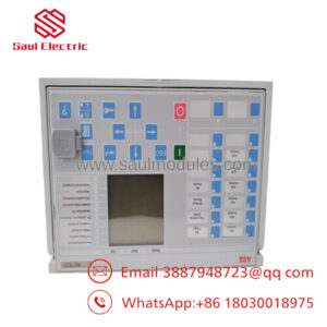
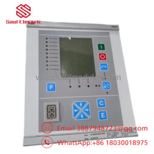
The ABB UFC911B101 3BHE037864R0101 is a specialized high-voltage interface and control board developed to link processing intelligence with high-power converter segments in massive electrical drives and excitation units, such as the legacy ACS600 or matching UNITROL infrastructure. This module manages critical conditioning paths, translating delicate control rack logic inputs into the hardened, high-current signaling demands necessary to coordinate drive power phases safely.
Plant systems maintenance teams favor the UFC911B101 due to its high physical isolation parameters, which decouple downstream control networks from potential high-voltage feedback transients. By handling signal conversion through a ruggedized component architecture, the board preserves system data integrity and timing precision under the heavy electrical stress and electromagnetic noise typical of metal-rolling mills, mining hoists, and high-capacity marine propulsion applications.
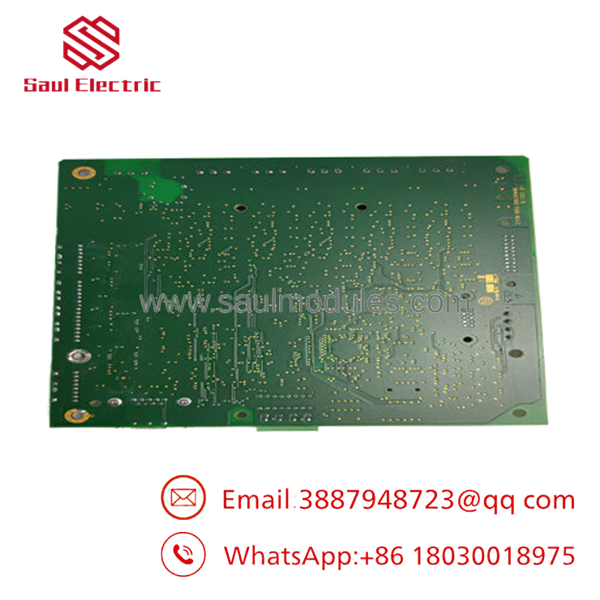
- UFC911B101
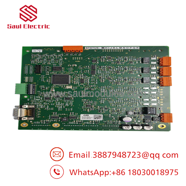
- UFC911B101
Installation & Configuration Guide
Stage 1: Pre-Installation Preparation (Estimated Time: 15 Minutes)
- ⚠️ Safety First: Drive inverter backplanes and high-voltage interface cabinets hold lethal potential energy. Coordinate with production dispatchers to confirm safety isolation. Lock out and tag out (LOTO) all main three-phase AC input breakers, auxiliary 24 VDC supply feeds, and any external bus supplies. Wait at least 15 minutes for intermediate DC link capacitors to discharge to a zero-voltage state. Verify complete energy dissipation using a properly rated multimeter directly across the bus points before touching terminals.
- Tools Required: Grounded static-control (ESD) wrist strap, insulated PH1/PH2 screwdrivers, fiber-optic cleaning apparatus, digital multimeter, labels for incoming control wires.
- Data Backup: Log into the drive application manager software. Save a master snapshot of all tuning variables, speed curves, power parameters, and communications module mappings to your laptop. Note or photograph any manual jumpers or slide configurations present on the installed card face.
Stage 2: Removing the Old Module (Estimated Time: 15 Minutes)
- Affix your ESD wrist strap to a verified, unpainted cabinet ground point.
- Label and remove low-voltage auxiliary connections, multi-pin signal terminal blocks, and ground wires.
- Gently disconnect all optical connections. Avoid pinching or tight radii bends (<30 mm). Apply matching dust protection plugs to both the cable endpoints and the open board fiber ports immediately.
- Unscrew the retention frame screws pinning the interface card frame to the drive housing.
- Pull the board straight forward out from its support guide tracks to safeguard the rear alignment pins from bending or binding.
- ⚠️ Note: Keep the decommissioned module on a clean anti-static mat nearby for comparison of structural hardware updates and component configurations.
Stage 3: Installing the New Module (Estimated Time: 15 Minutes)
- Keep the grounded ESD wrist strap securely connected while removing the new UFC911B101 card from its anti-static shield containment bag.
- Configuration Clone (Crucial): Meticulously audit all hardware-level configurations, matching any address jumpers, internal jumpers, or micro-switches to the precise state of the decommissioned board. Misplaced jumper pins can lead to immediate logic failure alerts or cause the system to drop the component off the drive bus network.
- Slide the card chassis down the guiding track assembly, checking alignment with the rear coupling until the card sits firmly home.
- Tighten the structural board anchors down completely to ensure solid, low-impedance frame grounding to the cabinet matrix.
- Use an optical click-cleaner on the fiber line endpoints, clear away the dust plugs, and snap each cable into its labeled RX/TX fiber port receptacle.
- Self-Checklist:
- [ ] Onboard micro-switches and configuration jumpers perfectly mimic the pulled card.
- [ ] Card frame is flush and securely screwed into the drive rack ground plane.
- [ ] Fiber cables are cleaned, clicked into place, and routed with gentle curves.
Stage 4: Power-On & Testing (Estimated Time: 20 Minutes)
- Pre-Power Check: Measure resistance between the card logic power inputs and the main frame chassis ground to rule out direct dead shorts across internal rails.
- Power-On Steps:
- Energize the local 24 VDC control/auxiliary power breakers only. Do not engage the primary high-voltage three-phase motor/excitation supply.
- Monitor the initial power LED indicators. The card should complete basic initialization loops inside of 30 seconds. A stable green state proves general board readiness, while active red indicators or missing link lamps imply data stream loop errors or initialization blocks.
- Establish a connection via your drive software workspace. Poll the hardware map to ensure that the interface component version registers seamlessly with the controller software.
- Perform an output handshake test, confirming logic tracking commands and safety interlock state transmission through the card before applying high-voltage power.
- ⚠️ Troubleshooting Note: If the drive controller issues an immediate “Drive Communication Time-Out” warning after power-up, check for microscopic dust inside the optical receiver terminals or inspect the fiber lines for inverted RX/TX positions.
Frequently Asked Questions (FAQ)
Can the interface board be hot-swapped while the drive system is running?
Absolutely not. Removing this card breaks the critical communication and isolation pathways between the drive control computer and the active high-voltage sections. Doing so drops phase synchronization signals instantly, causing an immediate overcurrent trip or an unmanaged system shutdown that can damage the internal power semiconductor array. Always power down the entire machine block before swapping parts.
What is the distinction between this board’s part numbers ( and 3BHE037864R0101)?
They denote the identical physical industrial asset. represents the functional model engineering layout series identifier, while 3BHE037864R0101 functions as the exact corporate inventory number (PNC) used within the global logistics and build records database. Either code confirms a direct drop-in replacement match.
Is this board genuinely new, given that the ACS600 and matching drive lines are mature?
Yes. Our inventory consists of verified New Original / New Surplus components. These modules are gathered from uncommissioned infrastructure projects, plant expansion overstocks, or strategic spares liquidations. They are unused, have spent their entire lifecycle inside climate-regulated storage facilities within sealed anti-static wrapping, and are verified free of aging traces.
Why does your team focus so heavily on the grounding screws of this specific card?
Because the functions as a high-voltage interface layout. It acts as a safety shield between high-potential power stages and digital control tracks. Without secure frame ground continuity through the structural mounting points, the card cannot properly shunt common-mode noise and high-frequency switching EMI, which leads to signal errors or potential component failure.
What happens if the replacement board fails immediately after commissioning?
Every module we supply comes with a comprehensive 1-year replacement warranty. If the component exhibits operational faults or logic failure under standard, documented operating configurations within 12 months from delivery, we will supply an identical replacement module or issue a full refund if replacement stock is exhausted.

 Start Chat


