





Description
Key Technical Specifications
| Parameter | Specification Value |
| Manufacturer | ABB |
| Model Number | UNS0867A-P,V2 |
| Part Number | HIEE405246R0002 |
| Circuit Board Revision | Version 2 (V2) |
| Signal Transmission Media | Fiber-optic links (HFBR series connectors) |
| Auxiliary Supply Input | 24 V DC (nominal, ±10%) |
| Gate Drive Output Channels | Dual independent gate control pathways |
| Isolation Rating | Galvanic separation up to 2.5 kV AC |
| Feedback Monitoring | Short-circuit, overcurrent, and collector-emitter voltage (V_{ce}) sensing |
| Form Factor | Proprietary Eurocard/rack-mount slide-in module |
| Operating Temperature | 0 to +60 °C (forced air cooling recommended) |
Product Introduction & Supply Chain Strategy
The ABB UNS0867A-P,V2 HIEE405246R0002 is a specialized power electronics control and gate driver board utilized within large-scale industrial excitation and drive systems, such as the UNITROL and MEGADRIVE series. This hardware functions as the direct electrical interface between low-voltage microprocessor control logic and high-power thyristor or IGBT semiconductor assemblies. By converting optical firing inputs into high-energy electrical gate pulses while monitoring real-world desaturation faults, it plays a vital role in preventing catastrophic component failures in high-voltage environments.
From a supply chain continuity perspective, keeping this specific V2 hardware variant on-site as a New Surplus asset represents a critical capital mitigation policy. Because this board directly dictates power semiconductor commutation, relying on low-cost refurbished boards introduces an unacceptable layer of risk. Used power electronics boards often carry micro-fractures in solder joints and compromised optocouplers caused by prolonged thermal cycling in dense cabinets. Sourcing a verified New Surplus assembly protects your capital infrastructure from expensive secondary damage and ensures full OEM-level insulation integrity.
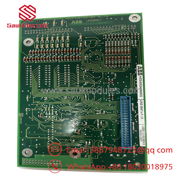
- UNS0867A-P,V2 HIEE405246R0002
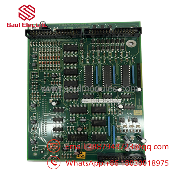
- UNS0867A-P,V2 HIEE405246R0002
Installation & Configuration Guide
Stage 1: Pre-Installation (Prep & Safety)
- Initiate full lock-out/tag-out (LOTO) protocols on the primary medium-voltage supply line feeding the inverter or excitation bridge assembly.
- Allow a minimum of 20 minutes for internal DC link filter capacitors to fully discharge through their automated bleed resistors. Verify zero residual voltage across the bus bars with a calibrated high-voltage meter.
- Fasten a grounded anti-static wrist strap to your person to protect the board’s high-sensitivity CMOS components from electrostatic damage.
- Document all fiber-optic link channel mappings and reference any hardware-configured jumper blocks present on the existing module frame.
Stage 2: Removal
- Disconnect the optical fiber cables gently by pulling on the outer connector body; never kink or bend the optical lines past their minimum bend radius.
- Unfasten the front-panel captive retention screws securing the Eurocard module to the sub-rack structure.
- Grip the injector/ejector handles firmly, applying even pressure to back the board out of its backplane connection without twisting the PCB.
- Place the removed module inside a dedicated static-shielding bag immediately for diagnosis or backup tracking.
Stage 3: Installation (Clone & Seat)
- Inspect the replacement UNS0867A-P,V2 board to ensure its onboard configuration jumpers match the exact layout of the original hardware asset.
- Align the top and bottom edge margins of the PCB card with the sub-rack plastic card guides.
- Slide the board slowly inward until you meet the backplane socket resistance, then push the ejector levers inward firmly to compress the multi-pin connector into the backplane.
- Hand-tighten the front-panel captive screws to secure the module ground connection against the frame.
Stage 4: Power-On & Testing
- Re-engage the fiber-optic links, ensuring each connector clicks cleanly into place and no dust contamination is visible on the cable ferrule tip.
- Apply control-side 24 V DC power while leaving the main medium-voltage three-phase bridge supply isolated.
- Verify that the auxiliary diagnostic power LEDs on the board front display a steady green state, indicating normal internal power rail regulation.
- Trace the fiber-optic receiver status using system diagnostics to confirm proper handshake signals with the master application processor before applying load.
Firmware/Software Versions & Upgrade Notes
The UNS0867A-P,V2 HIEE405246R0002 relies primarily on hardwired configuration parameters, logic matrices, and pre-programmed onboard array logic rather than operational runtime file downloads. The V2 designation indicates a distinct hardware layout revision that features enhanced noise immunity filters and improved isolation barriers over original V1 editions.
When executing an emergency replacement, ensure you are swapping like-for-like hardware variations. Introducing a legacy V1 variant into a system designed for V2 boards can lead to gate timing offsets or false overcurrent trips because of different propagation delay times within the signal isolation circuitry. Do not attempt component modification or chip swaps on these gate driver modules without a verified schematic matrix from the factory.
Frequently Asked Questions (FAQ)
Why is it critical that this board be “New Surplus” rather than a refurbished unit?
Gate driver boards run under continuous thermal stress inside power conversion cubicles. A refurbished board may have cleaned surfaces, but its internal isolation transformers and optocouplers have already endured millions of high-voltage commutation cycles. Only a New Surplus board guarantees full dielectric performance and insulation life, preventing unexpected cross-conduction that can explode a multi-thousand-dollar IGBT phase module.
What is the operational significance of the “V2” marking on this part number?
The V2 suffix represents a technical hardware update applied by the OEM to optimize signal propagation speed and upgrade noise filtration. This board is not always backward-compatible with older V1 sub-rack mounting layouts if the backplane pin definitions were altered. Always audit the existing system part number tag to ensure an exact revision match before purchasing.
Can I clean the optical ports if dust enters them during an extended installation window?
Yes, but you must use specialized tools. If dust settles inside the optical transceiver ports, clean them using dry, instrument-grade compressed air or specialized lint-free fiber swabs dampened with pure isopropyl alcohol (greater than 99% purity). Never use standard cotton swabs or tap water, as they leave conductive residue and fibers that distort the optical firing command.
How does the board communicate firing faults back to the central controller?
The board utilizes a dedicated duplex fiber-optic loop or designated backplane fault pins to send immediate feedback to the primary processing unit. If it detects a desaturation condition or a drop in auxiliary gate voltage, it halts the firing pulse within microseconds and alerts the system controller to trigger an emergency trip sequence.
Does this board carry internal parameters that require a software download during setup?
No. The ,V2 is a hardware-configured interface board. It functions based on component-level logic and jumper settings. It does not contain an independent operating system file or software application flash layer, meaning it is ready to run immediately once jumpers are matched and physical installation is complete.


 Start Chat


