





Description
Key Technical Specifications
| Parameter | Value |
|---|---|
| Model | XVC517AE10 |
| ABB Order Number | 3BHB004744R0010 |
| Manufacturer | ABB |
| Product Type | Gate Driver Unit (MV-GDR) |
| Primary Function | IGBT gate drive and protection |
| Application | ABB medium-voltage variable speed drives |
| Input Supply | 24 V DC (application dependent) |
| Protection Functions | Overcurrent, overvoltage, undervoltage monitoring |
| Mounting | Drive cabinet plug-in module |
| Operating Temperature | Approximately −40 °C to +70 °C |
| Weight | Approximately 2 kg |
| Country of Origin | Sweden (commonly listed) |
Compatibility Note: XVC517AE10 is used as a dedicated gate driver in ABB medium-voltage drive systems. Compatibility depends on the complete drive platform, hardware revision, and firmware. Always verify the ABB order number 3BHB004744R0010 before replacement.
Product Introduction
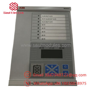
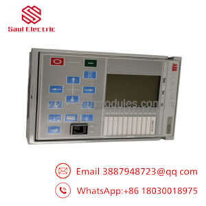
ABB XVC517AE10 (3BHB004744R0010) is a Gate Driver Unit designed for ABB medium-voltage variable frequency drives. The module converts low-level control commands into isolated gate-drive pulses for high-power IGBT devices while continuously monitoring drive protection conditions.
In field service, this module is typically replaced during preventive maintenance or after a semiconductor failure. Successful replacement depends on matching the exact hardware revision and verifying the associated power stack before commissioning. A physically compatible board is not always electrically compatible with every MV drive revision.
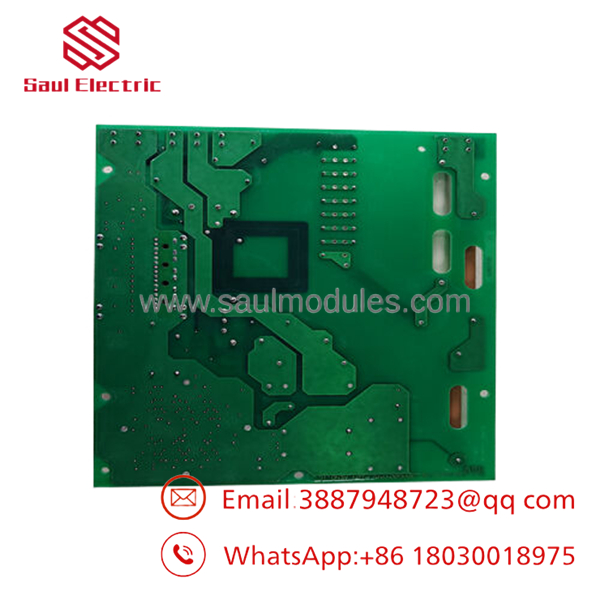
- XVC517AE10 3BHB004744R0010
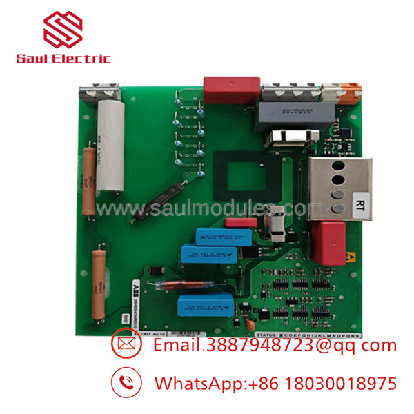
- XVC517AE10 3BHB004744R0010
Installation & Configuration Guide
Stage 1: Pre-Installation Preparation (Estimated Time: 15 Minutes)
⚠️ Safety First
- Notify plant operations and schedule drive downtime.
- Isolate incoming medium-voltage and auxiliary control power.
- Apply Lockout/Tagout (LOTO).
- Wait for DC bus capacitors to discharge completely. Confirm with a properly rated voltmeter before opening the cabinet.
Tools Required
- Grounded ESD wrist strap
- PH1/PH2 screwdriver
- Fluke 115 or equivalent multimeter
- Insulated gloves
- Wire labels
- Smartphone for documentation
Data Backup
- Record drive firmware version.
- Save drive parameter files.
- Photograph cable routing and connectors.
- Record board location and hardware revision.
- Document any jumper or configuration settings.
Stage 2: Removing the Old Module (Estimated Time: 10 Minutes)
- Open the drive cabinet.
- Disconnect fiber optic and signal connectors carefully.
- Label every cable before removal.
- Release retaining screws or locking clips.
- Remove the board evenly without twisting.
- Inspect connectors for discoloration, loose pins, or arc damage.
⚠️ Do not discard the old module until the replacement has completed full operational testing.
Stage 3: Installing the New Module (Estimated Time: 15 Minutes)
- Wear an ESD wrist strap before handling the board.
- Verify the complete part number:
- XVC517AE10
- 3BHB004744R0010
- Configuration Clone (Critical)
- Match hardware revision.
- Verify jumper positions if applicable.
- Inspect fiber optic connectors.
- Confirm all power and feedback connectors are correctly seated.
- Install the board evenly into its mounting position.
- Tighten retaining hardware.
- Reconnect every connector according to the photographs.
Self-Checklist
- Correct ABB order number
- Hardware revision verified
- Fiber optic cables connected
- Connectors locked
- ESD procedures followed
Stage 4: Power-On & Testing (Estimated Time: 30 Minutes)
Pre-Power Inspection
- Verify no loose hardware remains inside the cabinet.
- Check auxiliary power supply.
- Confirm connector orientation.
Power-Up Procedure
- Energize auxiliary control power only.
- Observe board status LEDs.
- Verify communication with the main drive controller.
- Apply medium-voltage supply after diagnostics complete.
- Perform low-speed motor test.
- Verify gate pulse synchronization.
- Monitor fault history and protection status.
⚠️ Troubleshooting Note
- Red Fault LED: Hardware revision or protection fault.
- Drive trips immediately: Inspect IGBT stage and fiber optic feedback.
- No gate pulses: Verify auxiliary supply voltage and communication with the main control board.
Frequently Asked Questions (FAQ)
Q1. Can be replaced while the drive is energized?
No.
Medium-voltage drives store hazardous energy even after power removal. Wait until the DC bus is fully discharged and verify zero voltage before handling the gate driver. Attempting a live replacement can damage the power stack and create a serious safety hazard.
Q2. What does the actually control?
It generates isolated gate-drive pulses for the drive’s IGBT power semiconductors while monitoring protection conditions such as overcurrent, undervoltage, and abnormal switching events. It is a critical interface between the drive controller and the power stage.
Q3. Is this module still manufactured?
The is commonly supplied through industrial spare-parts channels. Depending on the drive generation and regional availability, many units are offered as New Original surplus or tested replacement stock rather than current production.
Q4. What should I verify before ordering?
Confirm:
- ABB order number (3BHB004744R0010)
- Hardware revision
- Drive model
- Cabinet serial number
- Firmware version
- Existing gate driver revision
Even within the same ABB drive family, different hardware revisions may not be interchangeable.
Q5. Why are New Surplus units less expensive than factory pricing?
Most New Surplus inventory originates from cancelled projects, OEM excess inventory, or strategic spare-part stock. These modules have never been commissioned but may have been stored for several years. Ask for serial-number verification, inspection photos, and a functional test report before purchase.
Q6. What quality inspections should be completed before shipment?
A thorough quality process should include:
- OEM label and serial number verification
- PCB inspection for corrosion or repair marks
- Power-on functional test using a compatible ABB drive test bench
- Gate pulse output verification
- Fiber optic communication test
- Continuous burn-in under load
- Insulation resistance testing where applicable
- ESD-safe packaging with QC documentation
Test videos and photographs should be available upon request.
Q7. What is the most common field installation mistake?
Ignoring the condition of the power stage after a gate-driver failure.
I’ve seen engineers replace the gate driver only to have the new board fail immediately because an IGBT had already shorted. Before installing a replacement , measure the IGBT stack, inspect the snubber circuits, and verify there are no short circuits in the power section. That extra 15 minutes can prevent another expensive failure and unnecessary downtime.

 Start Chat


