





Description
Key Technical Specifications
| Parameter | Value |
|---|---|
| Model | YPQ110A |
| ABB Part Number | 3ASD573001A5 |
| Manufacturer | ABB |
| Product Type | Mixed I/O Board (ULMA I/O Module) |
| Primary Function | Analog and digital input/output processing |
| Compatible Systems | ABB Application Controller / ULMA platforms |
| I/O Interface | Local I/O bus via ribbon cable |
| Installation | Plug-in PCB |
| Dimensions | Approximately 306 × 245 × 40 mm |
| Weight | Approximately 0.76 kg |
| Country of Origin | Sweden |
| Lifecycle Status | Legacy spare part |
Compatibility Note: ABB documentation indicates the YPQ111A is the successor to the YPQ110A and can operate with the same application program, making it the recommended upgrade path in many installations. Hardware compatibility should always be confirmed before replacement.
Product Introduction
ABB YPQ110A (3ASD573001A5) is a mixed analog and digital I/O board designed for ABB application controllers and ULMA automation systems. It extends local process I/O by handling field signals through the controller’s I/O bus, providing deterministic communication between field devices and the application controller.
This board is primarily encountered in legacy ABB control systems where long service life makes spare-part availability important. During replacement, verify the controller type, I/O bus configuration, and hardware revision before commissioning to minimize downtime.
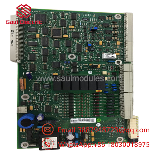
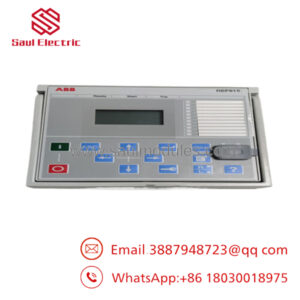
- YPQ110A
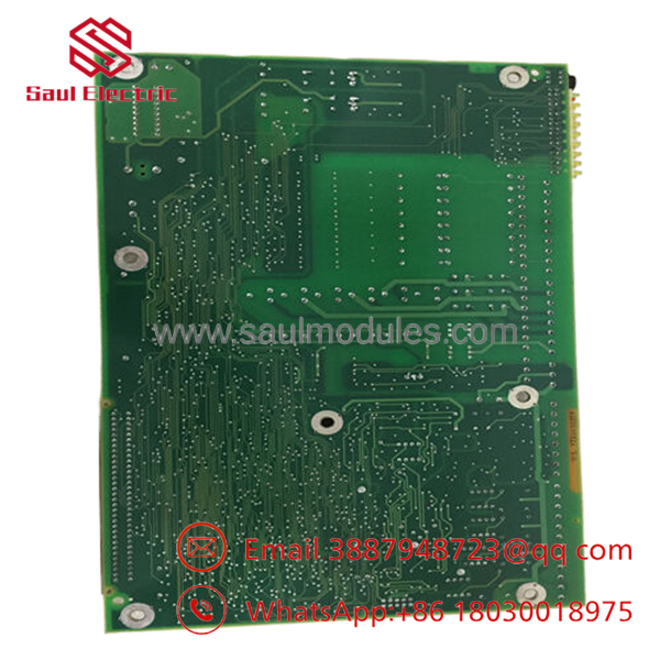
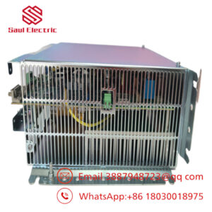
- YPQ110A
Installation & Configuration Guide
Stage 1: Pre-Installation Preparation (Estimated Time: 10 Minutes)
⚠️ Safety First
- Notify plant operations of the scheduled shutdown.
- Bring the controlled process to a safe operating state.
- Apply Lockout/Tagout (LOTO).
- Wait at least five minutes for all internal power supplies to discharge.
Tools Required
- Grounded ESD wrist strap
- PH1 screwdriver
- Fluke 115 digital multimeter
- Wire labels
- Smartphone for documentation
Data Backup
- Export the application controller configuration.
- Record the slot location.
- Photograph all ribbon cable connections.
- Save the application software and I/O mapping.
- Document any jumper or switch settings.
Stage 2: Removing the Old Module (Estimated Time: 10 Minutes)
- Open the control cabinet.
- Label every cable before disconnecting.
- Carefully unplug the 64-pin ribbon cable and other connectors.
- Release the retaining hardware.
- Remove the board straight out without twisting.
- Inspect the backplane and ribbon cable connectors for bent pins or contamination.
⚠️ Keep the original board until the replacement has completed functional testing.
Stage 3: Installing the New Module (Estimated Time: 10 Minutes)
- Wear a grounded ESD wrist strap.
- Verify:
- Model: YPQ110A
- Part Number: 3ASD573001A5
- Configuration Clone (Critical)
- Restore the original application configuration.
- Verify I/O bus cable orientation.
- Confirm slot position.
- Check jumper settings if applicable.
- Install the board firmly into the connector.
- Secure all mounting hardware.
- Reconnect the ribbon cable and remaining connectors.
Self-Checklist
- Correct ABB part number
- Ribbon cable orientation verified
- Board fully seated
- Configuration restored
- ESD precautions followed
Stage 4: Power-On & Testing (Estimated Time: 20–30 Minutes)
Pre-Power Inspection
- Verify auxiliary supply voltage.
- Check ribbon cable installation.
- Confirm there are no loose tools inside the cabinet.
Power-Up Procedure
- Energize the controller.
- Observe the board status LEDs.
- Verify the controller recognizes the I/O board.
- Download the saved configuration if required.
- Test every analog and digital channel.
- Confirm watchdog and communication status.
- Verify process values before returning the system to service.
⚠️ Troubleshooting Note
- Red fault LED: Check watchdog timeout or firmware compatibility.
- No I/O updates: Inspect the 64-pin ribbon cable and I/O bus connection.
- Incorrect signal values: Verify channel mapping and scaling before replacing hardware. ABB’s upgrade documentation notes that the watchdog disables outputs if updates stop, so communication faults should be investigated before assuming board failure.
Frequently Asked Questions (FAQ)
Q1. Can the be hot-swapped?
No.
The board should only be replaced with the controller powered down. Removing it while energized can interrupt the local I/O bus and may damage the controller or board.
Q2. What is the primary function of the ?
The is a mixed I/O board that processes both analog and digital signals for ABB application controllers. It connects to the local I/O bus through a 64-pin ribbon cable and exchanges process data with the controller.
Q3. Is there a replacement for the ?
Yes. ABB published an upgrade document identifying the YPQ111A as the replacement board. The same application program can generally be used, although hardware compatibility and system configuration should be verified before installation.
Q4. What should I verify before ordering?
Confirm:
- ABB Part Number (3ASD573001A5)
- Controller model
- Hardware revision
- I/O bus configuration
- Ribbon cable type
- Existing application software version
Never order based only on the PCB appearance.
Q5. Why is New Surplus inventory less expensive than factory pricing?
Most New Surplus boards originate from cancelled projects, OEM excess inventory, or strategic spare-part stock. Although unused, every board should undergo serial-number verification, visual inspection, power-on testing, and I/O communication validation before shipment.
Q6. What inspections should be completed before shipment?
A comprehensive quality procedure should include:
- OEM serial number verification
- Visual PCB inspection
- Power-on functional test
- Local I/O bus communication verification
- Analog and digital I/O simulation
- Continuous burn-in test
- Insulation resistance test (>10 MΩ where applicable)
- ESD-safe packaging with QC approval
Test photos and functional reports should be available upon request.
Q7. What is the most common field installation mistake?
Replacing the board without checking the I/O ribbon cable.
I’ve seen technicians replace a only to discover the real problem was an oxidized or partially seated 64-pin ribbon cable. Before installing a replacement, inspect every connector, clean the contacts if appropriate, and verify the cable orientation. Those checks often resolve intermittent I/O faults without replacing a functioning board.

 Start Chat


