





Description
Product Introduction & Engineering Value
The 651T-0600 is intended for a common instrumentation problem: an existing 4–20 mA two-wire signal needs to reach a second destination, but directly connecting the circuits could introduce ground-loop problems or allow a fault on the receiving loop to affect the original measurement circuit. Acromag specifically recommends the 651T-0600 for retransmitting a two-wire process signal to a second location.
This is a signal-conditioning device, not a PLC analog-input module. It does not replace the controller’s AI card. Its job is to sit between instrumentation loops and provide an electrically isolated retransmission path.
Technical Specifications
| Specification | 651T-0600 |
|---|---|
| Input signal | 4–20 mA DC |
| Output signal | 4–20 mA DC |
| Number of channels | 1 |
| Input type | Two-wire process current |
| Output type | DC current |
| Output limiting | 36 mA |
| Output compliance | Psupply = 12 V + (0.02 × Rload) |
| Maximum operating temperature | 70°C / 158°F |
| Minimum operating temperature | -25°C / -13°F |
| Mounting | DIN rail |
| Enclosure | UL94 V-2 nylon type 6.6 polyamide, NEMA Type 1 |
| Terminal wiring | AWG 14–22; AWG 12 stranded only |
| Dimensions | Approximately 1.05 W × 4.68 H × 4.35 D in. |
| Approx. metric dimensions | 26.7 × 118.9 × 110.5 mm |
| Approvals | CE, UL, cUL |
The published Acromag data identifies the input and output as 4–20 mA, specifies a 36 mA output limit, and gives an operating range of -25 to 70°C.
Acromag documentation gives the enclosure dimensions at approximately 26.7 × 118.9 × 110.5 mm.
Isolation Is the Point
The 651T-0600 should not be evaluated merely as a device that converts “4–20 mA to 4–20 mA.” The important engineering function is isolation.
Acromag describes the 600T family as isolated transmitters and specifically notes that the independent signal circuits prevent interaction between channels. The company’s application material also describes isolation as a means of breaking ground loops and protecting control-room equipment from transient signals.
Output-Loop Power Arrangement
One detail deserves special attention during replacement.
Acromag describes the 651T-0600 as a two-wire output-loop-powered device with a sinking output. The module derives operating power from the output loop rather than functioning like a conventional four-wire, independently powered analog transmitter.
That means the receiving side of the loop must provide the appropriate power arrangement.
Acromag gives the output compliance relationship as:
Psupply = 12 V + (0.02 × Rload)
This relationship should be checked against the actual receiving instrument, PLC/DCS analog input, wiring resistance, and available loop voltage before installation.
Practical Example
Suppose the retransmitted signal is feeding a 250 Ω analog input.
The approximate minimum supply requirement based on the published relationship is:
12 V + (0.02 × 250 Ω) = 17 V
This is why simply checking whether the receiving AI accepts “4–20 mA” is insufficient. The complete loop power budget has to be evaluated.
Typical Applications
1. Retransmitting a Process Measurement
This is the primary application documented by Acromag.
A two-wire transmitter may already feed the plant’s primary DCS input. The 651T-0600 can retransmit that 4–20 mA measurement to another destination such as:
- Chart recorder
- PLC analog input
- Secondary DCS input
- Remote display
- Data-acquisition system
- Process monitoring equipment
Acromag explicitly illustrates this configuration in its 600T application documentation.
2. Breaking Ground Loops
When two pieces of control equipment reference different electrical grounds, directly extending a current signal can introduce unwanted circulating currents or measurement errors.
An isolated transmitter provides a separation point between the original process loop and the receiving loop.
3. Process and Instrumentation Systems
The 651T-0600 is applicable to standard 4–20 mA measurements such as:
- Pressure
- Flow
- Level
- Temperature
- Speed
Acromag uses these measurement types in its documented 600T application examples.
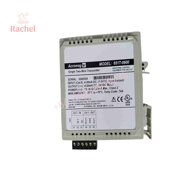
651T-0600
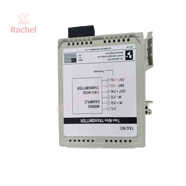
651T-0600
Field Application & “Trench” Experience
A plausible plant scenario:
A pressure transmitter feeds a DCS analog input correctly. Engineering later adds a PLC-based condition-monitoring system that needs the same pressure signal. Connecting the PLC input directly to the existing loop introduces an unexpected offset and intermittent instability.
The maintenance team initially suspects the pressure transmitter.
A better approach is to separate the instrumentation problem from the signal-distribution problem. The original transmitter loop should remain intact, while the 651T-0600 provides the isolated retransmission path to the second destination.
This is a representative engineering scenario, not a claim about a specific customer installation.
Niche Applications
The 651T-0600 is particularly useful where:
- A legacy DCS must share signals with a newer PLC.
- A process transmitter must feed both control and recording equipment.
- A ground-loop problem exists between two control cabinets.
- A remote monitoring system must receive an existing process-current signal.
- Hazardous-area instrumentation requires signal isolation at the control-system boundary.
Acromag also documents use of its 600T isolators in gas-detection applications, including retransmission of signals from remotely mounted gas sensors.
Installation & Wiring Considerations
Verify the Loop Architecture First
Before replacing the module, identify:
- Original transmitter
- Original 4–20 mA loop
- 651T-0600 input terminals
- Output-loop power source
- Receiving analog input
- Cable resistance
- Total receiving-loop load
The 651T-0600 is not a generic powered analog repeater. Its output-loop power arrangement matters.
Check Input Loading
Acromag documentation specifies an input-loop load of approximately 75 Ω maximum, corresponding to about a 1.5 V DC drop at full scale in the documented application.
This should be included when calculating the original transmitter’s loop burden.
Check Output Compliance
The receiving side needs sufficient voltage to operate the 651T-0600 and the receiving load.
Do not commission the device solely because the multimeter shows continuity.
Verify the complete 4–20 mA loop under:
- 0% signal
- 25% signal
- 50% signal
- 75% signal
- 100% signal
Calibration
The 600T series uses zero and span adjustment for field calibration. Acromag documentation describes periodic verification of the isolator’s zero and span as part of maintenance.
A useful maintenance procedure is:
- Apply a calibrated 4.00 mA input.
- Verify output.
- Apply 12.00 mA.
- Verify midpoint response.
- Apply 20.00 mA.
- Verify full-scale output.
- Check return to 4.00 mA.
- Record deviation.
For a critical measurement loop, calibration should be performed with a traceable current source and the actual receiving-loop configuration where practical.
Veteran’s Tech Trap Guide
⚠️ Trap #1 — Treating It as a Normal 4-Wire Isolator
The 651T-0600’s output-loop-powered/sinking arrangement is a defining characteristic.
Do not substitute a four-wire isolator without checking the power architecture.
PRO TIP: Draw the current loop on paper before installing the replacement. If you cannot identify where the output-loop power comes from, stop the installation and resolve that first.
⚠️ Trap #2 — Confusing 651T-0600 With 653T-0600
These are not the same device.
- 651T-0600: one input / one isolated retransmitted output
- 652T-0600: two input/output channels
- 653T-0600: one input / two isolated outputs
Acromag explicitly distinguishes these three configurations.
⚠️ Trap #3 — Ignoring Loop Burden
A 4–20 mA receiver may have a perfectly valid analog-input specification while the complete loop still lacks sufficient voltage.
Calculate:
Available supply voltage − transmitter/module drops − wiring drop − receiving-load drop
before declaring the loop compatible.
QA & Testing SOP
For a New Surplus or refurbished 651T-0600, inspect:
Identification
- Acromag nameplate
- Exact 651T-0600 model
- Serial/date information where present
- Terminal-block configuration
- DIN-rail mounting hardware
Visual Inspection
Check for:
- Cracked enclosure
- Damaged terminal blocks
- Corrosion
- Contaminated PCB
- Damaged adjustment potentiometers
- Loose terminals
- Evidence of excessive heat
Electrical Functional Test
A proper test should verify:
| Input | Expected Output |
|---|---|
| 4.00 mA | Approximately 4.00 mA |
| 8.00 mA | Approximately 8.00 mA |
| 12.00 mA | Approximately 12.00 mA |
| 16.00 mA | Approximately 16.00 mA |
| 20.00 mA | Approximately 20.00 mA |
The exact acceptance tolerance should follow the applicable Acromag specification and the plant’s calibration standard rather than an arbitrary reseller tolerance.
Also verify operation across the intended output-loop load.
New Surplus Authenticity
For procurement, request photographs of the actual unit, not a generic catalog photograph.
Verify:
- Acromag label
- 651T-0600 model number
- Serial/date information
- Terminal blocks
- Enclosure condition
- Packaging
- Supplier warranty
- Test report, if advertised as tested
A supplier’s “New Surplus” classification should not automatically be interpreted as a current Acromag factory warranty.
Acromag continues to list 651T-0600 in its current environmental compliance documentation as a “Single 2-Wire Isolator,” which provides strong manufacturer-level confirmation of the exact model identity.
Spare-Parts Procurement Strategy
For a plant with multiple 4–20 mA isolation points, the 651T-0600 is relatively straightforward to stock because its function is clearly defined.
Recommended inventory classification:
Criticality: Medium to High, depending on whether failure interrupts control or merely monitoring.
Preferred spare: Tested New / New Surplus
Acceptable alternative: Tested Refurbished
Avoid: Untested used units for safety- or production-critical loops
Maintain a record of:
- Installed loop application
- Input transmitter type
- Receiving AI card
- Output-loop supply voltage
- Typical load resistance
- Calibration date
- Spare serial number
- Last functional test
This makes future troubleshooting considerably faster.
FAQ
What is the Acromag 651T-0600?
It is a single-channel, two-wire isolated 4–20 mA transmitter/isolator in the Acromag 600T Series.
Does the 651T-0600 convert 4–20 mA to another signal?
No. Its normal function is 4–20 mA input to isolated 4–20 mA output. The value is signal isolation and retransmission, not a change from current to voltage or digital data.
Is it single-channel?
Yes. Acromag identifies 651T-0600 as the single-channel model. The 652T-0600 is the dual-channel version.
Is the 651T-0600 DIN-rail mountable?
Yes. Acromag identifies the 651T-0600 as a DIN-rail-mounted device, with approximately 26.7 × 95.3 × 110.5 mm body dimensions in its published mechanical drawing.
What temperature range does it support?
The published specification gives an operating range of -25 to 70°C (-13 to 158°F).
Can I replace a 651T-0600 with a 652T-0600?
Not as a direct catalog-number substitution without checking the installation. The 652T-0600 is a two-channel device and may have a different terminal arrangement and wiring requirements. If the application only requires one channel, the exact 651T-0600 remains the correct reference part.
Procurement Description
Acromag 651T-0600 600T Series Single-Channel Two-Wire Isolated Transmitter, 4–20 mA DC Input, Isolated 4–20 mA DC Output, DIN-Rail Mount, Industrial Signal Conditioner/Loop Isolator.
Recommended purchasing note: Verify the exact 651T-0600 model, terminal configuration, output-loop power arrangement, physical condition, and functional 4–20 mA test before accepting the unit as a production spare.

 Start Chat


