





Description
Product Introduction & Engineering Value
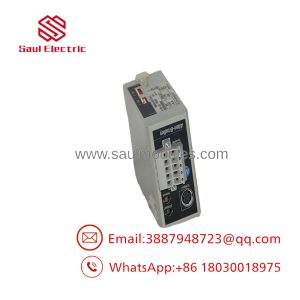
The Allen-Bradley 1753-L32BBBM-8A is the highest I/O capacity controller in the GuardPLC 1800 family. Built specifically for SIL 3 / Category 4 safety applications, this standalone safety controller combines dual-microprocessor architecture with built-in hardware fault detection to immediately force affected safety outputs into a known safe state upon detecting a system anomaly.
Featuring 24 digital inputs, 8 digital safety outputs, 8 unipolar analog inputs, and 2 high-speed counter channels, the 1753-L32BBBM-8A eliminates the need for sprawling safety relays on complex machines. A standout feature of this model is its integrated Modbus communication option, enabling seamless non-safety diagnostic and status data exchange with plant HMIs, standard PLCs, and SCADA monitoring networks.
Technical Specifications
| Specification | Parameter Value |
| Controller Series | GuardPLC 1800 |
| Operating Voltage | 24V DC (18V to 30V DC range), 8A max supply |
| User Memory | 250 KB User Program Memory / 250 KB Data Memory |
| Digital Inputs | 24 Inputs (24V DC nominal, 3.5 mA on-state current) |
| Digital Outputs | 8 Outputs (Output 4 & 8: 1.0A @ 60°C; Channels 1-3, 5-7: 0.5A rated) |
| Analog Inputs | 8 Unipolar Analog Inputs |
| High-Speed Counters | 2 Counters (24-bit resolution, 3 inputs per counter) |
| Communication Options | GuardPLC Ethernet Safety Network & Modbus Protocol |
| Enclosure Rating | IP20 |
| Dimensions & Weight | 114 mm x 257 mm x 80 mm (4.49″ x 10.1″ x 3.15″); ~1.2 kg (2.6 lbs) |
| Operating Temperature | 0°C to 60°C (32°F to 140°F) |
Field Application & The “Trench” Experience
In a metal stamping line utilizing robotic part transfer, an unexpected safety circuit trip caused intermittent E-stop lockouts. The diagnostic log on the 1753-L32BBBM-8A controller identified an internal cross-fault on a pair of dual-channel safety light curtain inputs. After confirming the external field wiring was intact, technicians traced the issue to a degraded channel on the controller’s input board. Swapping in a bench-tested 1753-L32BBBM-8A controller and downloading the GuardPLC safety project via GuardPLC OPC Server / RSLogix restored full safety trip functionality and cleared the line fault in under 40 minutes.
- Robotic Workcell Safety Cells: Monitoring light curtains, safety mats, gate interlocks, and two-hand control stations.
- Automotive Stamping Presses: Controlling E-stop circuits and press safety valves requiring high-current output channels (up to 1.0A).
- Process Skid Safety Interlocking: Utilizing the 8 analog inputs to monitor safety-critical pressure and temperature thresholds while transmitting status via Modbus to a main process PLC.
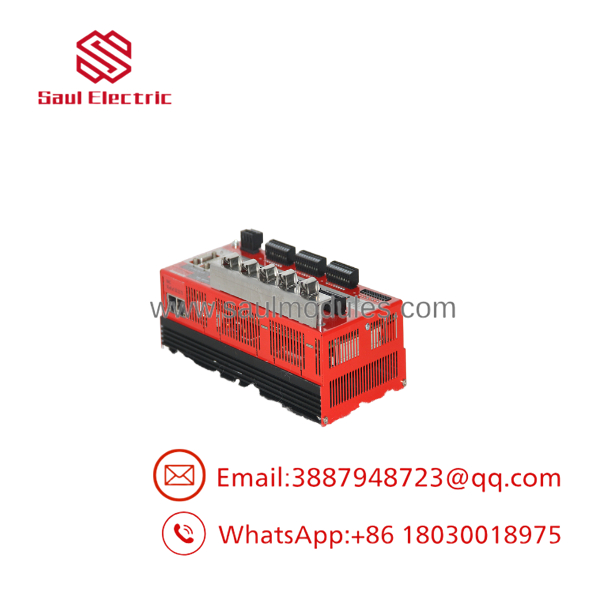
- 1753-L32BBBM-8A
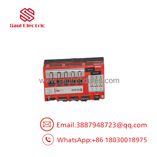
- 1753-L32BBBM-8A
Transparency SOP: QA & Testing
- Terminal Block & Hardware Physical Inspection: Checking all screw terminal blocks, ground shield plate attachment, IP20 housing clips, and status LED indicators.
- 24V DC Power & Voltage Range Verification: Applying 24V DC bus power across the main terminals to confirm internal dual-processor power regulation and fault-circuit readiness.
- Dual-Channel Input & Output Load Audit: Testing all 24 digital inputs, verifying state transitions on the 8 analog channels, and testing 0.5A and 1.0A load capacities on output channels 1–8 under simulated fault conditions.
- Modbus Network & Thermal Burn-In Test: Exercising Modbus data polling alongside GuardPLC safety logic execution inside an environmental chamber for 12 hours at elevated operating temperatures.
The Veteran’s Tech Trap Guide
- ⚠️ Non-Isolated I/O Design: Notice that the digital inputs, digital outputs, analog inputs, and high-speed counter channels on the 1753- are not electrically isolated. Care must be taken when routing field wiring alongside noisy AC motor drives or unshielded cables to prevent ground loops and induced noise from tripping safety inputs.
- PRO TIP: Channel Current Rating Differences: Output channels 4 and 8 are rated for 1.0 Amp continuous current at 60°C, whereas channels 1–3 and 5–7 are rated for 0.5 Amps. Always route higher-draw loads (such as heavy contactor coils or large safety solenoid valves) to channel 4 or channel 8 to prevent thermal overload trips.
- ⚠️ Strict Safety Firmware & Configuration Matching: When replacing a 1753- controller, you must download the exact safety project file with identical checksum and node configuration. Standard non-safety download procedures do not apply—the GuardPLC safety programming software verifies safety signatures prior to permitting RUN mode.
Dynamic FAQ
Q: What programming software is used for the 1753-?
A: The 1753- GuardPLC 1800 controller is programmed using Rockwell Automation’s GuardPLC Software Systems (e.g., GuardPLC System Software / RSLogix GuardPLC).
Q: What is the main difference between the 1753- and other GuardPLC controllers?
A: The 1753- offers the highest total I/O density in the GuardPLC family (32 I/O: 24 inputs, 8 outputs) along with 8 unipolar analog inputs and onboard Modbus communication capabilities.
Q: Does the 1753- support analog safety inputs?
A: Yes. It includes 8 onboard unipolar analog inputs designed to monitor process variables like temperature, pressure, or flow in safety-critical applications.
Q: Are replacement 1753- modules fully tested before shipment?
A: Yes. Every module undergoes dual-processor fault diagnostic checks, I/O channel load testing across all 32 points, analog calibration audits, and Modbus communication bench testing.

 Start Chat


