





Description
Product Introduction
The Allen-Bradley 1771-OFE1 is a 4-channel analog voltage output module designed for the 1771 Universal I/O platform used with PLC-5 processors and 1771-ASB remote I/O chassis drops. It receives 12-bit digital values across the chassis backplane via Block Transfer Write (BTW) instructions and converts them into proportioned analog voltage control signals.
Offering selectable operating ranges (such as \pm10VDC, 0–10VDC, or 1–5VDC), the 1771-OFE1 is built to drive precise speed commands to variable frequency drives (VFDs), position control valves, damper actuators, and chart recorders. Its onboard D/A converters feature electrical isolation between backplane logic and field wiring to eliminate ground loops in complex process environments.
Key Technical Specifications
| Parameter | Value |
| Output Channels | 4 Individually Configurable Voltage Channels |
| Voltage Output Ranges | \pm10VDC, 0 to +10VDC, +1 to +5VDC |
| D/A Resolution | 12-Bit (1 part in 4095) |
| External Auxiliary Power | 24VDC Nominal (20 to 28VDC) @ 150 mA max |
| Backplane Current Draw | 1.5 A @ 5VDC (Series A/B) | 1.2 A @ 5VDC (Series C) |
| Max Output Current | 10 mA per channel |
| Load Impedance | 1 k\Omega Minimum |
| Data Format | BCD or Binary (Configured via Block Transfer) |
| Conversion Rate | ~2.5 ms for all 4 channels |
| Optical Isolation | 1500 VAC (Field to Backplane) |
| Field Wiring Arm | 1771-WA 18-Pin Field Wiring Arm |
Application Scenarios & The “Trench” Experience
The Trench Story
During a retrofitted boiler commissioning run, a primary combustion fan controlled by a 1771-A3B expansion rack suddenly drops its speed command to zero whenever large motor contactors pull in nearby. The technician discovers the 1771-OFE1 channel was set for a 0–10VDC drive reference without using twisted-shielded pair cabling, allowing high-frequency EMI to corrupt the analog reference signal. Re-landing the speed reference on shielded 2-conductor cable, grounding the shield strictly at the 1771-WA wiring arm ground post, and re-scaling the Block Transfer Write (BTW) logic stabilizes the VFD speed loop instantly.
Specific Applications
- VFD Speed References: Sends 0–10VDC or \pm10VDC velocity commands to AC drives and DC servo drives across processing plants.
- Proportional Valve Actuation: Regulates positioners on hydraulic and pneumatic control valves in chemical and fluid handling loops.
- Dampers & Airflow Control: Drives 1–5VDC position commands to air dampers and draft fan actuators in HVAC/boiler systems.
- Recorder & Display Driving: Feeds analog chart recorders, panel meters, and graphic display meters on control room consoles.
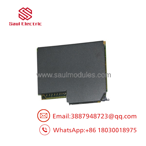
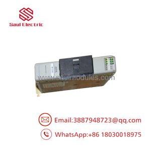
- 1771-OFE1
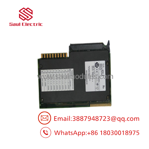
- 1771-OFE1
Transparency SOP: Quality Assurance & Testing
Every 1771-OFE1 analog output module undergoes a comprehensive calibration and load bench test prior to stock placement:
- Card-Edge & Component Inspection: We clean gold backplane card-edge contacts, check board capacitors, and inspect operational amplifiers for heat discoloration.
- Backplane & Logic Boot: The module is placed in a live 1771 rack with a PLC-5 controller to confirm 5VDC power draw and backplane Block Transfer initialization.
- Four-Channel Voltage Sweep Test: Each channel is commanded through 0%, 25%, 50%, 75%, and 100% output spans using Block Transfer Write (BTW) data files. Output voltages are measured using a calibrated digital multimeter (6.5-digit precision).
- External 24VDC Power Loop Test: The module’s auxiliary 24VDC input power terminals are stressed to confirm D/A converters stay within 0.1\% full-scale accuracy across voltage swings (20–28VDC).
- Load Resistor & Noise Burn-In: Channels are tested under a 1 k\Omega resistive load for two hours to verify amplifier stability and verify ripple noise remains well under specification limits.
The Veteran’s Tech Trap Guide
- ⚠️ Requires External 24VDC Auxiliary Power: Unlike standard digital output cards, the 1771- will not generate analog output voltages without an external 24VDC power supply connected to terminals on the 1771-WA wiring arm. If the front panel LEDs look normal but all channels read 0VDC, check your external 24VDC supply first.
- ❗ Do Not Confuse 1771- (Voltage) with 1771-OFE2 (Current): The is strictly a voltage output module (\pm10V, 0–10V, 1–5V). If your field actuators require a 4–20mA current loop signal, you MUST use the 1771-OFE2 or 1771-OFE3 module instead.
- ⚠️ Block Transfer Write (BTW) Programing is Mandatory: Analog data is not transferred through standard 1-slot or 2-slot image tables. You must execute Block Transfer Write (BTW) and Block Transfer Read (BTR) instructions in your PLC-5/ControlLogix ladder logic to configure range scaling, data format (BCD vs. Binary), and command values.
- ❗ Shield Grounding Best Practices: Always use individually shielded twisted-pair cables for analog voltage lines. Ground the cable shield at the 1771 chassis end ONLY. Leaving shields ungrounded—or grounding them at both ends—invites ground loops that introduce voltage offsets into sensitive 0–10V signals.
Frequently Asked Questions
Q: What is the main difference between the 1771-, 1771-OFE2, and 1771-OFE3?
- 4-channel Voltage Output (\pm10V, 0–10V, 1–5V)
- 1771-OFE2: 4-channel Current Output (4–20mA)
- 1771-OFE3: 4-channel Selectable Current/Voltage Output
Q: Which field wiring arm is required for the 1771-?
The 1771- uses the 1771-WA 18-pin field wiring arm.
Q: What resolution does the 1771- provide?
It provides 12-bit resolution, which divides the output voltage range into 4,095 discrete counts.
Q: What happens if external 24VDC power is lost during operation?
If the external 24VDC auxiliary power supply drops out, the 1771- outputs will collapse to approximately 0VDC, and the module’s diagnostic LED will indicate a fault condition.
Q: Can I use a 1771- in a ControlLogix system?
Yes. The module can be installed in a 1771 chassis connected via a 1771-ASB remote I/O adapter back to a ControlLogix chassis equipped with a 1756-RIO scanner module.
Q: What warranty covers your surplus and refurbished 1771- modules?
Every 1771- module we ship includes our full 12-month replacement warranty. If a hardware fault or channel calibration drift occurs under normal operating conditions within 365 days of purchase, we replace the unit immediately from stock or issue a full refund.

 Start Chat


