





Description
Core Product Summary
The Basler Electric DECS-200-1L is a style of the DECS-200 Digital Excitation Control System, a microprocessor-based automatic voltage regulator (AVR) and total excitation control system in one enclosure. It controls the output voltage, vars, or power factor of a synchronous generator by varying the DC excitation applied to the generator’s exciter field through an internal pulse-width-modulated (PWM) power stage, and Basler describes it as suitable for virtually any size machine.
A single DECS-200 accommodates 32 Vdc, 63 Vdc, or 125 Vdc applications up to 15 Adc continuous (30 Adc for 10 seconds), with true RMS sensing on single- or three-phase generator voltage across four sensing ranges from 100 V to 600 V nominal. Voltage regulation accuracy is ±0.25% over the load range, and the system includes Field Current Regulation (manual) mode, var and power factor control modes, over- and underexcitation limiters, a stator current limiter, underfrequency/V/Hz limiting, soft start, paralleling compensation, an exciter diode monitor, and eight generator protection functions. Setup is from the backlit LCD front-panel HMI or the supplied Windows-based BESTCOMS software, with communications via front-panel RS-232 (ASCII), a side RS-485 port supporting Modbus protocol up to 4,000 feet, and optional autotracking between operating modes and between dual DECS-200 units. The unit is UL recognized, CSA certified, CE compliant, and DNV certified, and carries U.S. Patent 5,294,879.
Key Technical Specifications
| Parameter | Value |
|---|---|
| Product type | Digital Excitation Control System (microprocessor-based AVR and excitation controller) |
| Series / style | DECS-200 series, style DECS-200-1L (publication SZM-11, 9-10) |
| Controlled machine | Synchronous generator exciter field (brushless or static excitation applications) |
| DC output power | One unit accommodates 32 Vdc, 63 Vdc, or 125 Vdc applications up to 15 Adc |
| Rated continuous field voltage / current | 32 Vdc, 63 Vdc, or 125 Vdc at 15 Adc (depending on configuration) |
| Rated 10-second forcing | 50/100/200 Vdc at 30 Adc (per output range; up to 50% higher with 3-phase input or low field current) |
| Minimum field resistance | 2.13 Ω (32 Vdc), 4.2 Ω (63 Vdc), 8.3 Ω (125 Vdc) |
| Power stage | Pulse-width modulated (PWM) — improves performance with non-linear loads |
| Control power input (style selectable) | 16–60 Vdc (30 W); 85–132 Vac, 50/60 Hz (50 VA); 90–150 Vdc (30 W) |
| AC operating power | Single- or three-phase input, 50–500 Hz: 56–70 Vac (32 Vdc output, 780 VA), 100–139 Vac (63 Vdc output, 1570 VA), 190–277 Vac (125 Vdc output, 3070 VA); minimum voltage buildup 3 Vac |
| Generator voltage sensing | True RMS, single- or three-phase, four ranges: 100/120 V, 200/240 V, 400/480 V, 500/600 V nominal |
| Bus voltage sensing | Single-phase, same four ranges |
| Current sensing | 1 A and 5 A ranges, two-channel (phase) inputs; burden less than 1 VA (voltage, current, and parallel compensation) |
| Regulation accuracy | AVR mode ±0.25% over load range; steady-state stability ±0.1%; FCR mode ±1.0%; var mode ±2.0%; PF mode ±0.02 PF |
| Temperature drift | ±0.5% over 0 to 50 °C |
| Contact switching inputs | 11 inputs supplied with 24 Vdc for dry contacts (start, stop, AVR/FCR mode, raise/lower, var/PF enable, pre-position, alarm reset, unit/parallel, others) |
| Analog set point input | ±10 Vdc or 4–20 mA (selectable), e.g., for a power system stabilizer |
| Contact outputs | Watchdog, Start/Stop, Relays #1–3; make/break 7 A at 24 Vdc / 120/240 Vac, 0.7 A at 48 Vdc, 0.2 A at 125 Vdc; carry 7 A |
| Communications | COM0: front RS-232 (ASCII, 1200–19200 baud); COM1: side RS-232 for dual-unit autotracking; COM2: side RS-485, Modbus protocol, up to 4,000 feet |
| Metering | <1% accuracy for 12 generator parameters; real-time clock; 127-event sequence-of-events recording; 8 oscillographic records (6 variables, 600 points, COMTRADE format) |
| Limiters / protection | Overexcitation limiter (summing-point and takeover types), minimum excitation limiter, stator current limiter, field overvoltage (1–325 Vdc), field overcurrent (ANSI C50.13), generator over/undervoltage (ANSI C50.13), loss of field, loss of sensing, exciter diode monitor, watchdog |
| Surge withstand / fast transient | IEEE C37.90.1-1989; high potential per IEEE 421.3 |
| Operating / storage temperature | −40 to +60 °C / −40 to +85 °C |
| Environment | Salt fog per MIL-STD-810E Method 509.3; shock 15 G in three planes; vibration 5.0 G (53–500 Hz) |
| Dimensions | 8.08 in (205 mm) W × 6.76 in (171 mm) D × 12.0 in (304 mm) H |
| Weight | 14 lb (6.35 kg) |
| Agency approvals | UL recognized (Std. 508, file E97035);CSA certified (CAN/CSA-C22.2 名列前茅4, file LR23131); CE (EMC, LVD); DNV Standard 2.4; GOST-R; Byelorussian certified |
Detailed Product Overview
The DECS-200-1L sits between Basler’s smaller DECS-100-class regulators and the larger DECS-400/DECS-2100 platforms: it packages the complete excitation chain — sensing, regulation, a PWM power output stage, limiting, protection, and communications — in one 14-pound enclosure, intended for direct panel or enclosure mounting on medium-sized synchronous generators.
The defining electrical characteristic is the PWM power stage feeding the exciter field. Unlike phase-controlled SCR designs, PWM output holds its regulation performance with non-linear loads, and one physical unit covers 32, 63, or 125 Vdc field systems at up to 15 Adc continuous, with 10-second forcing to 30 Adc. This range spans most brushless exciter fields in the hundreds-of-kW to small-MW generator class, which is why Basler describes the platform as suitable for virtually any size machine: the same regulator model is reconfigured to the field voltage level rather than replaced with a different power rating. Selection therefore hinges on the field resistance and excitation voltage of the specific machine — the documented minimum field resistances are 2.13 Ω, 4.2 Ω, and 8.3 Ω for the 32, 63, and 125 Vdc ranges respectively, and the operating-power transformer (60, 120, or 240 Vac nominal, per the output range) must be matched accordingly.
Regulation performance is the product’s core specification: ±0.25% RMS voltage regulation from no-load to full-load, achieved with true RMS sensing and selectable single- or three-phase measurement, plus 20 preprogrammed PID stability settings with user-customizable tuning through the BESTCOMS PID selection program. Beyond the AVR, the unit runs four operating modes — AVR, FCR (manual field current regulation), var, and power factor — with internal autotracking so the inactive modes follow the active one, enabling bumpless transfers. That matters in practice: on loss of sensing, a protective scheme can transfer to FCR mode without a field disturbance, and the FCR mode remains a genuine backup channel because it regulates field current from the internal bridge rather than the sensing input.
The limiting and protection suite is what makes the device a “total excitation system” rather than a bare regulator: summing-point or takeover-style overexcitation limiting with on-line and off-line levels, an underexcitation limiter with internally generated or 5-point custom curves, stator current limiting, and eight protective functions (over/undervoltage, field overvoltage and overcurrent, loss of field, loss of sensing, and the exciter diode monitor for brushless machines). The oscillography and 127-event SER records, retrievable over BESTCOMS or Modbus, support commissioning — a voltage step-response record can be triggered directly from the software — and post-event analysis.
Style selection is the practical procurement issue. The DECS-200 was built in multiple styles whose suffix (here “-1L”) encodes the factory configuration, including control power option and installed features; the instruction manual’s style-number identification chart defines these characteristics. A replacement must be ordered by full style number, and where control power option C (120/125 Vac/Vdc) is used, redundant dual control power sources are supported with an isolation transformer on the AC input.
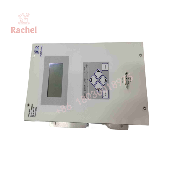
DECS-200-1L
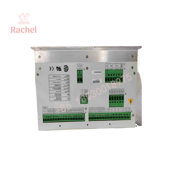
DECS-200-1L
Engineering Selection Highlights
- 32/63/125 Vdc at 15 Adc from one style — match the unit to the machine’s exciter field voltage and minimum field resistance (2.13/4.2/8.3 Ω); verify the 10-second forcing ceiling (30 Adc) covers the machine’s ceiling excitation requirement.
- AC operating power must match the output range — 56–70 Vac for the 32 Vdc output (780 VA), 100–139 Vac for 63 Vdc (1570 VA), 190–277 Vac for 125 Vdc (3070 VA), single or three phase, 50–500 Hz; three-phase input permits up to 50% higher DC output at low field currents.
- ±0.25% regulation with true RMS sensing — single- or three-phase sensing in four ranges (100 V to 600 V nominal) covers standard generator and bus voltages without external transformers in most installations.
- FCR (manual) mode with autotracking — provides a sensing-independent backup channel, and the optional dual-unit autotracking (with interconnection cable and freewheeling diode module) builds a fully redundant excitation system from two DECS-200 units.
- Limiters and ANSI-referenced protection built in — field overcurrent and generator over/undervoltage per ANSI C50.13, loss of field, loss of sensing, and EDM for brushless exciter diode monitoring reduce the need for separate protective devices in the excitation cubicle.
- Communications for SCADA and commissioning — RS-485 Modbus up to 4,000 feet, front RS-232 with BESTCOMS (settings, metering, PID selection, oscillography triggers), COMTRADE-format records viewable in BESTWAVE.
- Mounting environment breadth — −40 to +60 °C operation, salt fog per MIL-STD-810E, 15 G shock, and DNV marine certification make the style usable in offshore and marine generating sets, subject to the documented front-panel cutout and bracket hardware.
System Compatibility & Integration Requirements
| Item / Dependency | Verified Compatibility or Requirement | Practical Note |
|---|---|---|
| Controlled machine | Synchronous generator exciter field (brushless or static excitation) | EDM requires entry of generator and exciter pole counts (0–20 in steps of 2) |
| DC output | 32, 63, or 125 Vdc at 15 Adc continuous, 30 Adc for 10 s | Min. field resistance 2.13 / 4.2 / 8.3 Ω per range |
| AC operating power | 56–70 / 100–139 / 190–277 Vac, 1- or 3-phase, 50–500 Hz, matched to output range | Typically fed from the generator output via a power transformer; min. buildup 3 Vac |
| Control power (style selectable) | 16–60 Vdc (30 W), 85–132 Vac (50 VA), or 90–150 Vdc (30 W) | Style C (120/125 Vac/Vdc) supports redundant dual sources with isolation transformer BE31449-001 |
| Voltage/current sensing | Generator: single/3-phase, 100–600 V nominal in 4 ranges; current: 1 A / 5 A, <1 VA burden | Existing metering CTs usable for paralleling compensation (no dedicated CT required) |
| Paralleling compensation | Reactive droop or reactive differential (cross-current), 0–30% droop, 1 A or 5 A input | Line-drop compensation −30% to 0 using the same parameter |
| Set point control | Raise/lower contacts, pre-position contacts, ±10 Vdc or 4–20 mA auxiliary input (e.g., PSS), RS-232 ASCII or RS-485 Modbus | Traverse rates independently adjustable per mode |
| Dual-unit redundancy | Interconnection cable 9310300032 and DECS Freewheeling Diode Module 9293600101 | Side RS-232 (COM1) links primary and backup units for autotracking |
| Inrush limitation | ICRM-15 Inrush Current Reduction Module required when the source is already at the rated input level | Minimizes energization inrush into the power stage |
| Mounting hardware | Front panel mounting bracket 9360107100 | Per front-panel cutout drawing |
| Grounding | Hard-wired earth ground, minimum 12 AWG copper, to the rear ground terminal | Separate ground lead per unit recommended when installed with other devices |
| Certifications | UL (Std. 508), CSA, CE (EMC/LVD), DNV Std 2.4, GOST-R, Byelorussian | Surge withstand and fast transient per IEEE C37.90.1-1989 |
Dimensions, Mounting & Connection Notes
- Enclosure dimensions: 8.08 in (205 mm) wide × 6.76 in (171 mm) deep × 12.0 in (304 mm) high; weight 14 lb (6.35 kg).
- Front-panel (semi-flush) mounting using the front-panel mounting bracket, Basler P/N 9360107100; the datasheet provides the front-panel cutout dimension drawing.
- Front panel carries the backlit 64 × 128 pixel graphic LCD, six pushbuttons (including EDIT with five-minute auto-exit if changes are not saved), six LEDs (pre-position, lower limit, upper limit, null balance, internal tracking, edit), and the COM0 RS-232 9-pin connector.
- Side panels carry the COM1 RS-232 port (right side, dual-unit autotracking only) and the COM2 RS-485 Modbus port (left side, up to 4,000 feet).
- Earth grounding must be hard-wired with no smaller than 12 AWG copper wire to the ground terminal on the rear of the case; each unit in a multi-device panel should have its own lead to the ground bus.
- Operating power is typically taken from the generator output through a power transformer matched to the output range; when energizing from a source already at the regulator’s rated input voltage, the ICRM-15 module is required to limit inrush.
- Installation of the AC connection diagram and interconnection wiring follows the interconnect diagram in the product bulletin and the instruction manual (publication 9360100990).
- Environmental installation limits: −40 to +60 °C ambient, vibration up to 5.0 G (53–500 Hz), salt-fog-rated construction.
FAQ
What is the Basler -1L?
It is a style of the Basler Electric DECS-200 Digital Excitation Control System — a microprocessor-based automatic voltage regulator and complete excitation control system for synchronous generators, whose “-1L” suffix identifies the factory configuration as defined in the style number chart of the instruction manual.
What does the DECS-200 do?
It controls generator output voltage, vars, or power factor by regulating the DC excitation applied to the generator’s exciter field through an internal PWM power stage, and it limits and protects the machine with over/underexcitation limiters, stator current limiting, and eight protective functions.
What output voltage and current can it supply?
One unit accommodates 32 Vdc, 63 Vdc, or 125 Vdc applications up to 15 Adc continuous, with 10-second forcing of 30 Adc; minimum field resistances are 2.13, 4.2, and 8.3 ohms respectively for the three ranges.
How accurate is its voltage regulation?
±0.25% over the load range in AVR mode, with steady-state stability of ±0.1% and temperature drift of ±0.5% over 0–50 °C; FCR, var, and PF modes each carry their own documented accuracy (±1.0%, ±2.0%, and ±0.02 PF respectively).
What operating modes does it provide?
Four modes: automatic voltage regulation (AVR), field current regulation (FCR, the manual backup channel), var control, and power factor control — with internal autotracking between modes for bumpless transfer, and optional autotracking between two DECS-200 units.
How is it set up and monitored?
From the front-panel backlit LCD and pushbuttons, or via the supplied Windows-based BESTCOMS software over the front RS-232 port; remote monitoring uses the RS-485 port with Modbus protocol up to 4,000 feet. It stores 127 sequence-of-events records and 8 oscillographic records in COMTRADE format.
What power supplies does it need?
AC operating power matched to the output range (56–70, 100–139, or 190–277 Vac, single or three phase, 50–500 Hz) plus a style-selected control power input (16–60 Vdc, 85–132 Vac, or 90–150 Vdc).
Which approvals does it carry?
UL recognized per Standard 508 (file E97035), CSA certified, CE compliant (EMC and LVD), DNV certified per Standard 2.4, plus GOST-R and Byelorussian certification; surge withstand and fast transient immunity meet IEEE C37.90.1-1989.
Verification & Troubleshooting Notes
- Style verification first: confirm the full style number on the nameplate against the style identification chart in the instruction manual — control power option and installed features are encoded in the style, and substitutions can miswire the control power input.
- Front-panel LEDs: pre-position, upper/lower limit LEDs indicate the active mode’s set point state; the null balance LED confirms that inactive modes have tracked the active mode (a precondition for bumpless mode transfers); the internal tracking LED annunciate the autotracking state.
- Loss of sensing behavior: the loss-of-sensing protection is adjustable (0–100% of nominal voltage, 0–30 s delay) and the documented response to sensing failure is a transfer to FCR mode by protective relays — verify that the external scheme actually initiates this transfer, since FCR mode itself does not limit or protect against sensing loss.
- OEL and SCL behavior in FCR mode: in FCR mode the DECS-200 only announces that overexcitation or stator overcurrent conditions exist; it does not limit. Operators running manual mode after a transfer must control field current directly.
- Field overvoltage/overcurrent alarms: both are adjustable (1–325 Vdc with 0.2–30 s inverse delay; 0–16 Adc per ANSI C50.13) — nuisance alarms during startup often trace to settings not matched to the machine’s field parameters recorded during commissioning.
- EDM indication: the exciter diode monitor requires correct generator and exciter pole entries; incorrect pole settings produce false open/shorted diode indications on healthy machines (earlier firmware revisions corrected specific EDM nuisance indications on secondary units, so note the application firmware version, displayed via BESTCOMS, when diagnosing).
- Commissioning records: use BESTCOMS to trigger an oscillography record of the voltage step response, and check the 127-event SER log for the exact sequence of input/output changes and alarms around any disturbance before suspecting hardware.
- Grounding and power quality: inrush at energization from an already-rated source requires the ICRM-15 module, and the documented 12 AWG minimum ground lead must be respected — excitation-system misbehavior on weak supplies frequently traces to source impedance and grounding rather than the regulator.

 Start Chat


