





Description
Core Product Summary (Brand / Model / Key Attributes)
The Basler Electric DECS-200N-C1 is a style of the DECS-200N Negative Forcing Digital Excitation Control System, a multi-microprocessor-based automatic voltage regulator (AVR) intended for 63 Vdc and 125 Vdc generator excitation applications requiring up to 20 Adc of continuous field current. The unit integrates a six-thyristor (SCR) controlled rectifier bridge that provides negative field forcing up to 40 Adc, supporting high-response excitation systems and use with power system stabilizers.
The C1 style uses redundant control power inputs rated 125 Vdc nominal (90–150 Vdc, 30 W maximum) and 120 Vac nominal (82–132 Vac, 40 VA maximum, 50/60 Hz). AC operating power is accepted over 80–277 Vac, single- or three-phase. Regulation modes include automatic voltage regulation, manual field current regulation, var control, and power factor control, with internal autotracking between modes. Sensing covers generator voltages from 100/120 V through 500/600 V nominal (true RMS, single- or three-phase) and 1 A or 5 A current inputs. Communications are provided through an RS-232 service port and an RS-485 Modbus port. The housing measures 8.96 in wide × 7.94 in deep × 14.03 in high and weighs 14 lb (6.35 kg).
Key Technical Specifications
| Parameter | Value |
|---|---|
| Product type | Negative forcing digital excitation control system (AVR with built-in SCR bridge) |
| Series | DECS-200N |
| Continuous field current | 20 Adc (63 Vdc and 125 Vdc applications) |
| Maximum forcing current | 40 Adc (negative field forcing) |
| Minimum field resistance | 3.15 Ω at 63 Vdc; 6.25 Ω at 125 Vdc |
| Field output, 63 Vdc continuous | ‘+130/−105 Vdc (208 Vac 1-phase input); +120/−100 Vdc (120 Vac 3-phase input) |
| Field output, 125 Vdc continuous | ‘+240/−200 Vdc (240 Vac 1-phase input) |
| AC operating power (style X1) | 80–277 Vac, single- or three-phase, 50–160 Hz |
| Minimum residual buildup voltage | 24 Vac (1-phase); 12 Vac (3-phase) |
| Control power (style CX, C1) | 125 Vdc nominal, 90–150 Vdc, 30 W max; 120 Vac nominal, 82–132 Vac, 40 VA max, 50/60 Hz |
| Regulation accuracy (AVR mode) | ±0.25% over load range; steady-state ±0.1%; temperature drift ±0.5% (0–50 °C) |
| Regulation accuracy, other modes | FCR ±1.0%; var ±2.0%; power factor ±0.02 PF |
| Voltage sensing | True RMS, single- or three-phase; 100/120, 200/240, 400/480, 500/600 V nominal ranges |
| Current sensing | 1 A / 5 A, two channel inputs; burden < 1 VA |
| Analog set point input | ±10 Vdc or 4–20 mA |
| Switching inputs | 11 inputs, 24 Vdc dry contacts |
| Contact outputs | 5 programmable; make/break 7 A at 24 Vdc or 120/240 Vac; carry 7 A |
| Operating modes | AVR, FCR (manual), var, power factor; internal autotracking |
| Communications | COM0 front RS-232 (19200 baud, ASCII); COM1 side RS-232 (dual-unit autotracking); COM2 side RS-485 Modbus (1200–19200 baud) |
| Operating temperature | −40 °C to +60 °C |
| Storage temperature | −40 °C to +85 °C |
| Shock / vibration | 15 G shock; 5 G vibration (53–500 Hz) |
| Dimensions / weight | 8.96 × 7.94 × 14.03 in (228 × 202 × 356 mm); 14 lb (6.35 kg) |
| Approvals | cURus per UL 508 (file E97035) and CSA C22.2 名列前茅4; GOST-R; Republic of Belarus certification |
Detailed Product Overview
The DECS-200N-C1 belongs to the DECS-200N family, Basler Electric’s negative forcing line of digital excitation controllers. Unlike a conventional half-controlled exciter that can only reduce field current to zero, the DECS-200N’s six-thyristor bridge can actively pull current out of the generator field. With 20 Adc continuous capability and 40 Adc maximum forcing, the unit suits medium-sized machines where fast field suppression matters — for example, to improve stability margins in high-response excitation systems or to limit overspeed of the terminal voltage following load rejection.
The C1 designation identifies the control power style. Style C units accept redundant control power from two independent sources: a 125 Vdc battery-backed supply (90–150 Vdc, up to 30 W) and a 120 Vac source (82–132 Vac, up to 40 VA). This redundancy means the regulator keeps operating if either the station battery or the AC control supply fails, which is a common procurement requirement for critical generating units. Where the two control power sources are not electrically isolated, the BE31449-001 isolation transformer (120:120 Vac) is used.
Regulation is handled by four selectable operating modes. AVR mode holds generator terminal voltage to ±0.25% across the load range using true RMS sensing, and the underfrequency slope characteristic (0–3.0 P.U., adjustable in 0.1 increments) rolls the voltage reference back with frequency to avoid over-fluxing the machine. FCR mode provides manual field current regulation, and var and power factor modes hold reactive output at the generator terminals. Internal autotracking keeps the inactive mode’s reference aligned with the active one, so mode transfers — including transfers to manual during commissioning or after a sensing failure — do not produce a voltage step. A second DECS-200N can be paired for redundant automatic voltage regulation with dual-unit autotracking over the side RS-232 link.
Protection and limiting functions are extensive and configurable through the BESTCOMS software. Overexcitation is covered by both summing-point and takeover limiters, with levels adjustable up to 40 Adc. The underexcitation limiter uses a five-point customizable curve. Stator current limiting, field overvoltage (1–325 Vdc), field overcurrent coordinated with ANSI C50.13, generator over/undervoltage, loss of field, loss of sensing, exciter diode monitoring, watchdog, and failed-to-buildup supervision are all included. A sequence-of-events recorder stores 127 events, and eight oscillography records (6 variables, 600 points each, COMTRADE format) support post-event analysis without external test equipment.
The analog set point input (±10 Vdc or 4–20 mA) allows an external device such as a power system stabilizer to modulate the voltage reference, which is the standard method for adding damping to machines prone to local-mode or inter-area oscillations. The eleven 24 Vdc contact inputs and five programmable contact outputs integrate the regulator with plant control logic for raises, lowers, mode changes, and alarm reporting.
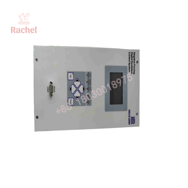
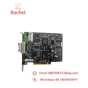
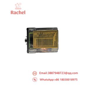
DECS-200N-C1
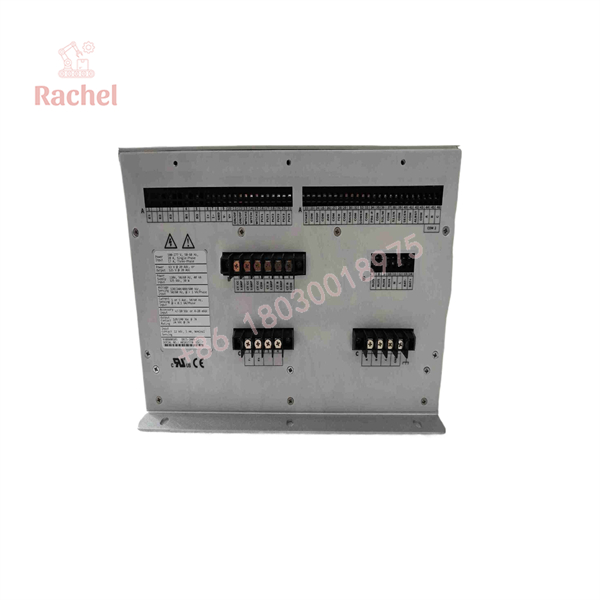
DECS-200N-C1
Dimensions, Mounting & Connection Notes
- Dimensions: 8.96 in (228 mm) wide × 7.94 in (202 mm) deep × 14.03 in (356 mm) high
- Weight: 14 lb (6.35 kg)
- Front panel: COM0 RS-232 service port (19200 baud, 8 data bits, no parity, 1 stop bit) for BESTCOMS connection
- Side ports: COM1 RS-232 for dual-unit autotracking; COM2 RS-485 Modbus (1200–19200 baud) for SCADA/PLC integration
- Contact ratings: programmable outputs make/break 7 A at 24 Vdc or 120/240 Vac; 0.7 A at 48 Vdc; 0.2 A at 125 Vdc; continuous carry 7 A
- Environment: operating −40 °C to +60 °C; storage −40 °C to +85 °C; shock 15 G; vibration 5 G over 53–500 Hz; salt fog qualified per MIL-STD-810E method 509.3
Engineering Selection Highlights
- 20 Adc continuous / 40 Adc forcing with negative field forcing — verify the generator field resistance is at least 3.15 Ω (63 Vdc systems) or 6.25 Ω (125 Vdc systems); fields below these values cannot be driven within the bridge’s ratings.
- Field output depends on AC source configuration — at 63 Vdc continuous, a 208 Vac single-phase source yields +130/−105 Vdc forcing and a 120 Vac three-phase source yields +120/−100 Vdc; at 125 Vdc continuous, use a 240 Vac single-phase source for +240/−200 Vdc. Match the supply transformer to the required forcing margin, noting the output figures assume a 10% source impedance.
- Redundant CX control power (C1 style) — the unit accepts 125 Vdc (90–150 Vdc) and 120 Vac (82–132 Vac) control power simultaneously; specify both sources if dual-supply continuity is a requirement, and include the BE31449-001 isolation transformer when the two sources are not independently isolated.
- Frequency range is style-dependent — the C1’s AC operating power is specified for 50–160 Hz; applications from sources outside this band require a different frequency style of the DECS-200N family.
- Residual buildup voltage — the unit needs at least 24 Vac (single-phase) or 12 Vac (three-phase) residual voltage to build up; generators with weak remanence should be evaluated for field flashing provisions, which the controller supports.
- Sensing covers standard PT secondaries — four voltage ranges (100/120 to 500/600 V) and 1 A/5 A CT inputs accept most machine configurations without external conversion hardware.
- BESTCOMS software dependency — configuration, limiting, limiter curve shaping, and oscillography retrieval require the Basler BESTCOMS Windows software; request the DECS-200N-CD media kit with the controller.
System Compatibility & Integration Requirements
| Item / Dependency | Verified Compatibility or Requirement | Practical Note |
|---|---|---|
| Generator field rating | 63 Vdc or 125 Vdc excitation systems, up to 20 Adc continuous | Minimum field resistance 3.15 Ω (63 Vdc) or 6.25 Ω (125 Vdc) |
| AC operating power | 80–277 Vac, single- or three-phase, 50–160 Hz (C1 style band) | Output values assume 10% source impedance; size the supply transformer accordingly |
| Control power | 125 Vdc (90–150 Vdc, 30 W) and 120 Vac (82–132 Vac, 40 VA, 50/60 Hz) | Redundant inputs; use BE31449-001 isolation transformer when sources are not isolated from each other |
| Voltage sensing | True RMS, 100/120, 200/240, 400/480, 500/600 V nominal, single- or three-phase | Select the range matching the PT secondary |
| Current sensing | 1 A or 5 A CT inputs, two channels, < 1 VA burden | Required for var and power factor modes and stator current limiting |
| External analog control | ±10 Vdc or 4–20 mA set point input | Interface point for a power system stabilizer or plant controller |
| Software | BESTCOMS Windows software (request DECS-200N-CD) | Required for setup, limiting, and oscillography retrieval |
| Redundant configuration | Dual DECS-200N units with autotracking | Interconnection via the side RS-232 (COM1) link |
| Human-machine interface | IDP-800 touch-screen HMI available as an accessory | Provides local set point adjustment and metering without a PC |
FAQ
What is the Basler -C1?
It is a style of the Basler Electric DECS-200N Negative Forcing Digital Excitation Control System — a multi-microprocessor-based automatic voltage regulator with an integrated six-thyristor controlled rectifier bridge for 63 Vdc and 125 Vdc generator excitation applications up to 20 Adc continuous.
What does negative field forcing mean in practice?
The six-SCR bridge can actively drive current out of the generator field rather than only reducing it to zero, with maximum forcing current of 40 Adc. This allows faster field suppression for high-response excitation systems.
What control power does the C1 style require?
The C1 uses the CX control power style: a nominal 125 Vdc input (90–150 Vdc range, 30 W maximum) and a nominal 120 Vac input (82–132 Vac range, 40 VA maximum, 50/60 Hz). Both can be connected simultaneously for redundancy.
Which operating modes does the DECS-200N-C1 provide?
Automatic voltage regulation (AVR), manual field current regulation (FCR), var control, and power factor control, with internal autotracking so transfers between modes occur without a voltage or field current step.
How accurate is voltage regulation?
AVR mode regulates to ±0.25% over the load range and ±0.1% steady-state, with temperature drift of ±0.5% over 0–50 °C. FCR mode is ±1.0%, var mode is ±2.0%, and power factor mode is ±0.02 PF.
What communications are available?
A front RS-232 service port (COM0, 19200 baud ASCII) for the BESTCOMS software, a side RS-232 port (COM1) for dual-unit autotracking, and a side RS-485 Modbus port (COM2, 1200–19200 baud) for supervisory systems.
Which protection and limiting functions are built in?
Summing-point and takeover overexcitation limiters, a customizable five-point underexcitation limiter, stator current limiter, field overvoltage and overcurrent protection, generator over/undervoltage, loss of field, loss of sensing, exciter diode monitoring, watchdog, and failed-to-buildup detection, plus a 127-event sequence-of-events recorder and eight COMTRADE oscillography records.
Which approvals does the DECS-200N-C1 carry?
cURus listing per UL 508 (file E97035) and CSA C22.2 名列前茅4, GOST-R certification, and Republic of Belarus certification, with high-potential testing performed per IEEE 421.3.
Verification & Troubleshooting Notes
- Unit will not build up generator voltage: confirm the residual voltage at the sensing terminals meets the 24 Vac (single-phase) or 12 Vac (three-phase) minimum; check that the active set point is not driven to zero by an active analog input or contact command; verify field flashing connections if the machine has weak remanence.
- No output to the field: verify the AC operating power source is within 80–277 Vac and within the 50–160 Hz band for this style; confirm the control power supply is live on at least one input; check the “failed to build up” and watchdog status via BESTCOMS or the status contacts.
- Mode transfer causes a voltage step: the autotracking function requires the inactive regulator to remain powered and tracking; verify the internal autotracking enable settings and, in dual-unit configurations, the COM1 RS-232 crossover connection between the two units.
- Regulation unstable at low frequency: confirm the underfrequency slope setting matches the generator’s V/Hz limit; the reference should roll back in proportion to frequency below the knee point to avoid over-fluxing.
- Modbus communication failure: verify COM2 wiring polarity, baud rate (1200–19200), and that the unit address in the supervisory system matches the BESTCOMS configuration; the front COM0 port uses fixed 19200 baud, 8 data bits, no parity, 1 stop bit for local service.
- Crowbar-fired or overexcitation alarms: read the oscillography record and sequence-of-events log before resetting; these events indicate the field or bridge reached a protective level, and the underlying cause (limiter settings, field resistance below the 3.15 Ω/6.25 Ω minimums, or a supply transformer sizing issue) should be corrected rather than bypassed.
- All commissioning and diagnostic work on the excitation system should be performed on a de-energized machine or under an approved generator test procedure, since the field circuit carries stored energy and the bridge output is not isolated from the AC supply.

 Start Chat


