





Description
Product Introduction & Engineering Value
The 107TL47 is built around a simple but important principle: an isolated IT power network can continue operating after a first insulation fault, but maintenance personnel need to know that the fault exists. The device continuously evaluates insulation resistance and provides an alarm when the configured response threshold is reached.
The documented version is for 230 VAC, 50–60 Hz systems and uses a single alarm relay with two changeover contacts. The device also provides visual operating and alarm indication.
Technical Specifications
| Specification | 107TL47 |
|---|---|
| Manufacturer | BENDER |
| Model | 107TL47 |
| Ordering Number | B922178 |
| Product Family | ISOMETER |
| Monitored System | Unearthed AC IT power system |
| Nominal Monitored Voltage | AC 230 V |
| Frequency | 50–60 Hz |
| Rated Insulation Voltage | AC 250 V |
| Rated Impulse Voltage | 2 kV |
| Response Value | 50–500 kΩ |
| Maximum Leakage Capacitance | 1 µF |
| Measurement Voltage / Current | 15 V / 63 µA |
| Internal Resistance | ≥240 kΩ |
| Internal Impedance | ≥200 kΩ |
| Alarm Relay | 1 relay, two changeover contacts |
| Relay Contact Rating | AC 250 V / 5 A |
| Panel Signal Output | 20 V |
| Current Output | 0–400 µA |
| Maximum Output Load | 3 VA |
| Ambient Temperature | −5 to +50 °C |
| Protection | IP30 internal / IP20 at connectors |
| Weight | Approximately 470 g |
The technical values above are supported by a distributor’s catalog information for the B922178 version.
A separate current inventory listing gives 73 × 99 × 75 mm dimensions and identifies the unit as a BENDER insulation-monitoring device with load-current and temperature-monitoring capability.
Important ordering distinction
BENDER documentation also lists 107TL47-1, ordering number B922179, with a different monitored-voltage arrangement of AC 0–230 V. The standard 107TL47 is listed as AC 230 V, 50–60 Hz / B922178.
Do not substitute 107TL47-1 merely because the model names look almost identical.
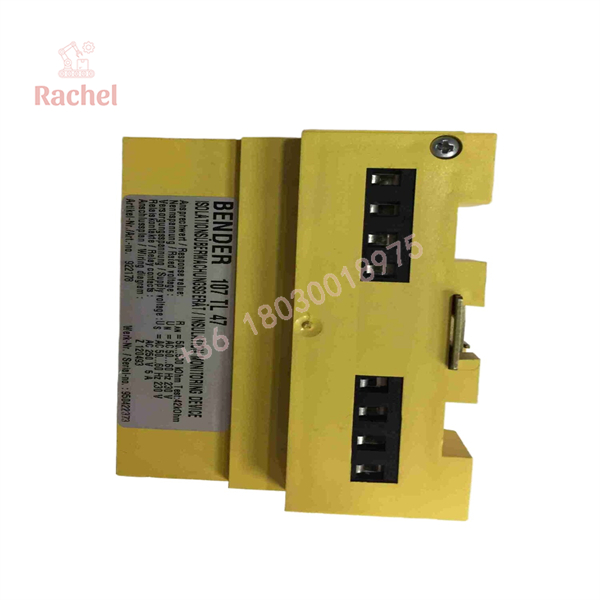
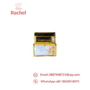
107TL47
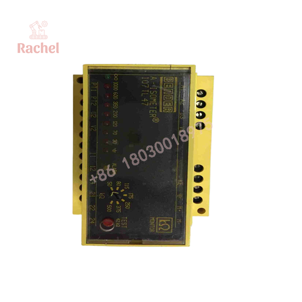
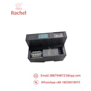
107TL47
Field Application & the “Trench” Experience
A hospital operating-room distribution system continues supplying power normally, but the insulation-monitoring alarm begins appearing intermittently.
The first reaction is often to look for a failed load.
That can waste hours.
With an IT power system, the insulation monitor is telling the maintenance team that the system’s insulation margin has deteriorated. The equipment can still be operating. The fault may be a damaged cable, moisture, a medical device, a heating element, or another connected load.
A technician checks the 107TL47 alarm indication and then isolates downstream circuits systematically. The alarm disappears when one branch is disconnected. The branch is investigated and the actual insulation fault is found.
That is exactly where an insulation monitor earns its place: it turns an invisible leakage problem into a maintainable alarm before the system reaches a more serious condition.
Specific Application Scenarios
- Hospital operating-room IT power systems where continuity of supply is important and the first insulation fault must be detected.
- Medical treatment areas supplied through isolated power systems in accordance with applicable medical electrical requirements.
- Isolation-transformer secondary networks where continuous insulation supervision is required.
- Legacy medical electrical distribution panels where an existing 107TL47 must be replaced without changing the original monitoring architecture.
The 107TL47 is specifically documented for medical-location IT systems under DIN VDE 0107 and is also associated with DIN EN 61557-8 requirements.
Transparency SOP: QA & Testing
For an insulation-monitoring device, “powers on” is not a meaningful acceptance test by itself.
1. Identity check
Verify:
- BENDER
107TL47- Ordering number B922178
- Supply configuration
- Serial number
- Terminal markings
2. Visual inspection
Check the enclosure, terminal blocks, LEDs, adjustment elements, and PCB for contamination, cracking, corrosion, or previous repair.
3. Supply verification
Apply the correct auxiliary supply specified for the particular installation and confirm normal operating indication.
4. Insulation simulation
Use an appropriate calibrated insulation-resistance test setup to simulate resistance between the monitored IT network and PE.
5. Response verification
Test representative resistance values across the configured response range and verify that the alarm activates at the expected threshold.
6. Relay verification
Confirm operation of the alarm relay and verify both changeover contacts.
7. Measurement-circuit check
Verify the measurement circuit and protective-earth connection monitoring where applicable.
8. Functional reset/test
Operate the device’s test/reset functions and verify that the alarm behavior matches the expected sequence.
A current used-equipment listing reports four units in stock, while another listing identifies a new unit.
The Veteran’s Tech Trap Guide
⚠️ Trap #1 — Confusing 107TL47 with 107TL47-1
This is the big one.
The documented ordering numbers are:
- 107TL47 → B922178 → AC 230 V, 50–60 Hz
- 107TL47-1 → B922179 → AC 0–230 V, 50–60 Hz
PRO TIP: Put the full model and ordering number on the purchase order.
⚠️ Trap #2 — Assuming the alarm means the monitor is defective
It may not.
An insulation alarm can be a legitimate indication of deteriorating insulation in the connected IT network.
Before replacing the monitor, isolate downstream circuits and verify the actual insulation resistance.
⚠️ Trap #3 — Testing with an ordinary multimeter
A basic resistance measurement is not a substitute for a controlled insulation-monitoring test.
The 107TL47 uses a defined measurement circuit, and the documented measurement voltage/current is 15 V / 63 µA.
PRO TIP: Use a calibrated resistance simulator or appropriate test equipment when validating the response threshold.
⚠️ Trap #4 — Treating relay contacts as the measurement circuit
The relay is the alarm output. It does not perform the insulation measurement.
The documented device has one alarm relay with two changeover contacts rated at AC 250 V / 5 A.
Dynamic FAQ
What is BENDER 107TL47?
It is an ISOMETER insulation monitoring device for unearthed AC IT power systems. The documented B922178 version is intended for 230 VAC, 50–60 Hz networks.
What is the BENDER 107TL47 ordering number?
The documented ordering number is .
What insulation resistance does it monitor?
The documented response range is 50–500 kΩ. The device continuously monitors the insulation condition of the unearthed IT system and generates an alarm when the configured response value is reached.
Is 107TL47 suitable for medical IT power?
Yes. The 107TL47 is documented for IT power systems in medical locations, including applications covered by DIN VDE 0107 and related medical electrical requirements.
Is New Surplus 107TL47 available?
Current secondary-market evidence shows both new and used units. One listing identifies a new BENDER 107TL47, while another has used units available.
For procurement, verify the physical nameplate and ordering number rather than accepting a generic “107TL47” catalog description.
How do I verify New Surplus authenticity?
Request photographs of the actual device showing the BENDER name, 107TL47 model, B922178 ordering number, serial number, terminals, front panel, and original packaging. The seller should explicitly classify the condition as New OEM, New Surplus/NOS, Refurbished, or Used-Tested.
What warranty should I request?
Warranty terms vary by supplier. One current supplier advertises a 12-month warranty, while used inventory is also available.

 Start Chat


