





Description
Product Introduction
The Bently Nevada 330500-02-00 Velomitor is a specialized piezoelectric velocity transducer engineered to measure absolute casing, housing, or structural vibration. Unlike traditional electrodynamic velocity sensors that rely on moving coils prone to wear and mechanical degradation, the 3300/50 Velomitor uses a solid-state piezoceramic element integrated with an internal accelerometer-to-velocity integrator circuit.
Configured with a 1/4-28 UNF integral mounting stud (-02) and standard unapproved agency rating (-00), this sensor provides a direct AC voltage output proportional to absolute vibration velocity. It integrates seamlessly into machinery protection monitoring systems (such as the Bently Nevada 3500, 2300, or 1900 series) and portable data collectors for predictive maintenance analysis on pumps, motors, gearboxes, and fans.
Key Technical Specifications
| Parameter | Options / Configuration Value |
| Mounting Thread Option (-02) | 1/4-28 UNF Integral Mounting Stud |
| Agency Approval Option (-00) | No Agency Approvals (Unclassified / Standard Area) |
| Sensitivity | 100 mV/in/s (3.94 mV/mm/s) ±5% at 80 Hz |
| Frequency Response | 4.5 Hz to 5.0 kHz (270 cpm to 300,000 cpm) ±3 dB |
| Amplitude Range | Up to 50 in/s (1270 mm/s) peak velocity limit |
| Power Requirements | 15 to 30 VDC (2 to 10 mA constant current loop power) |
| Connector Type | 2-Pin MIL-C-5015 Top-Mounted Hermetic Receptacle |
| Operating Temperature | -55°C to +121°C (-67°F to +250°F) |
| Case Material | 316L Stainless Steel (Hermetically Sealed) |
Application Scenarios & The “Trench” Experience
Picture this: It’s during peak summer load at a power generation station. A critical induced-draft boiler fan starts triggering intermittent high-casing vibration warnings on the main plant DCS. An old moving-coil velocity sensor on the bearing pedestal had jammed its internal spring coil from continuous vibration. Dropping in a rugged, solid-state Bently Nevada 330500-02-00 sensor restores precise 4.5 Hz–5 kHz broadband vibration tracking instantly—allowing the plant reliability team to identify a loose fan runner bolt before catastrophic bearing cage failure occurs.
- Electric Motors & Cooling Tower Fans – Absolute Casing Monitoring – Measures overall structural vibration on rolling-element bearing housings where shaft proximity probes cannot be installed.
- Horizontal Centrifugal Pumps – Impeller Vane Pass & Cavitation Tracking – Detects high-frequency hydraulic turbulence and casing velocity levels directly on pump volutes.
- Industrial Gearboxes – Gear Mesh Frequency Analysis – Captures solid-state AC velocity waveforms to feed predictive maintenance diagnostic software.
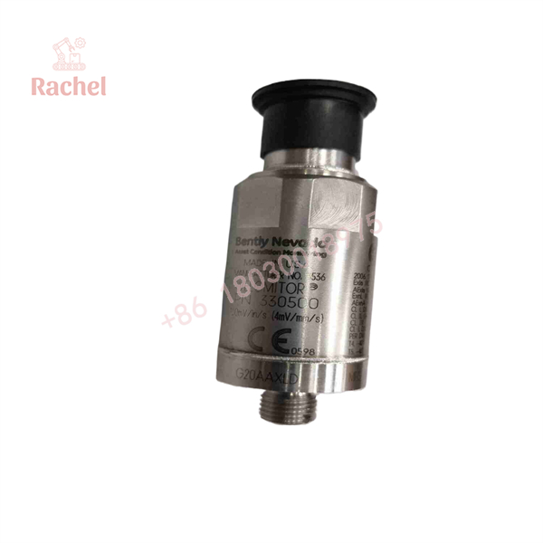
330500-02-00
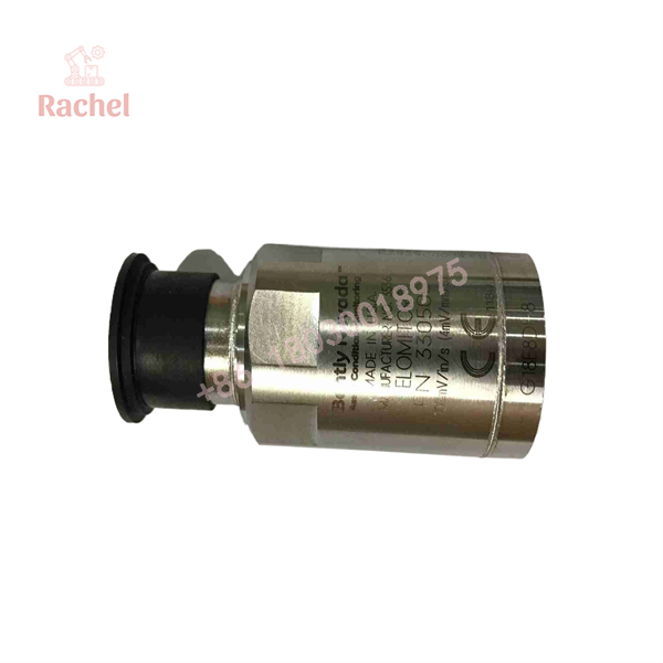
330500-02-00
Transparency SOP: Quality Assurance & Testing
We test every Velomitor unit on dedicated vibration calibration systems before shipment:
- Inbound Visual Inspection: Inspect the 316L stainless steel body, check the 1/4-28 UNF stud threads for damage, and verify MIL-C-5015 connector pin integrity.
- Current Bias Line Verification: Power the unit using a constant-current excitation supply and verify the DC bias voltage stays stable within nominal limits (10–14 VDC).
- Dynamic Response & Sensitivity Test: Mount the unit on a reference shaker table at 80 Hz (1.0 in/s peak acceleration/velocity input); verify output voltage reads 100 mV/in/s within ±5%.
- Noise Floor Check: Verify zero extraneous electrical noise spikes on the dynamic spectrum output before sealing.
- Final QC & Packaging: Install thread-protection caps, wrap in anti-static ESD packaging, and enclose in custom foam shipping cartons.
The Veteran’s Tech Trap Guide
- ⚠️ Mounting Stud Torque Value: Over-torquing the 1/4-28 UNF mounting stud during installation can crack or deform the internal crystal structure. Torque the sensor to 30 to 40 in-lbs (3.4 to 4.5 N·m) using a calibrated torque wrench and silicon grease on the mounting surface.
- ❗ Polarity and Constant Current Powering: The 330500 Velomitor requires a 2-wire constant-current loop power source (typically 2 to 10 mA, nominal 24 VDC). Pin A is Power/Signal (+) and Pin B is Common/Return (-). Reversing wiring connections will result in zero signal output.
- ⚠️ Cable Isolation & Armor Grounding: Always use twisted, shielded cable (such as Bently Nevada 9571 or 84661 cables). Ground the shield at the monitor end ONLY to prevent ground loop noise from degrading velocity readings.
- ❗ Low-Frequency Limitations: While the sensor frequency response extends down to 4.5 Hz (270 cpm), low-speed machinery operating below 300 RPM requires specialized low-frequency accelerometers/transducers rather than standard Velomitors.
Frequently Asked Questions (FAQ)
Q: What do the “-02” and “-00” option codes stand for?
A: -02 designates an integral 1/4-28 UNF threaded mounting stud. -00 indicates No Agency Approvals (intended for non-hazardous/standard industrial environments).
Q: Does the 330500 Velomitor require a separate Proximitor sensor or external driver?
A: No. The 330500 contains all integration and signal-conditioning electronics internally inside its 316L stainless steel body. It wires directly into monitor rack input cards or portable data collectors that supply constant-current power.
Q: What cable connector works with the 330500-02-00?
A: It requires a 2-socket MIL-C-5015 splash-proof connector assembly (such as the Bently Nevada 9571 series cable with boot seal).
Q: Can I mount this sensor in any physical orientation?
A: Yes. The solid-state piezo design allows the 330500 to be mounted vertically, horizontally, or at any angle without changing its calibration scale factor.

 Start Chat


