





Description
Product Introduction
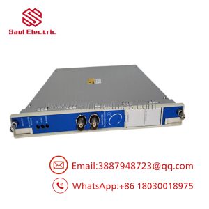
The Bently Nevada 3500/32 125720-01 is the main front card for the 4-Channel Relay Module in the 3500 Machinery Protection System. Operating as a full-height card, it takes alarm drive signals generated by adjacent monitoring modules (such as 3500/42M or 3500/40M) via the rack backplane bus and translates them into physical dry-contact relay state changes. These contacts trigger emergency shutdown trip circuits, sound local control room annunciators, or interface directly with ESD (Emergency Shutdown) PLCs.
Each channel on the 125720-01 circuit board is independently programmable using 3500 Rack Configuration Software. Engineers can construct voting logic schemes—such as 1-out-of-2, 2-out-of-2, or 2-out-of-3 combinations—combining Alert and Danger status bits from any channel across the rack. The board incorporates dual onboard microprocessors to continuously cross-check relay coil status and driver circuitry, preventing spurious trips and ensuring fail-safe action when actual machinery limits are breached.
Key Technical Specifications
| Parameter | Value |
| Part / Assembly Number | 3500/32 (Main Card P/N: 125720-01) |
| Manufacturer | Bently Nevada (Baker Hughes) |
| Module Type | 4-Channel Relay Main Control Card |
| Number of Relays | 4 physical relays per module |
| Contact Type | Double-Pole Double-Throw (DPDT) dry contacts |
| Contact Rating (Resistive) | 5 A @ 250 VAC / 5 A @ 30 VDC |
| Max Switching Power | 1500 VA AC / 150 W DC |
| Programmable Logic | AND / OR / voting logic across any rack monitor channel |
| Power Consumption | 5.8 Watts typical |
| LED Indicators | OK, Alarm Status, Individual Relay State LEDs (1–4) |
| Operating Temperature | -30°C to +65°C (-22°F to +149°F) |
| Storage Temperature | -40°C to +85°C (-40°F to +185°F) |
Application Scenarios & The “Trench” Experience
When a machinery protection relay fails, you face a dangerous dilemma: run without trip hardware or take an un-planned outage to fix it. We once supported a chemical plant where an old 125720-01 relay card failed during a severe lightning storm—welding channel 2’s output contacts shut and throwing continuous coil fault alarms. The operators had to jump out the master trip bus to keep the reactor blower running. We pulled a pre-tested 125720-01 card from surplus, pre-verified its contact resistance on the bench, swapped the module during a scheduled 1-hour maintenance window, and safely restored hardwired trip protection to their ESD system.
- Petrochemical Plants – Critical Compressor Trains – Executes 2-out-of-2 voting logic on radial vibration channels to trigger automatic emergency machine trips.
- Power Generation Facilities – Steam Turbine Generators – Actuates hardwired breaker trip coils directly when axial thrust position exceeds dangerous wear thresholds.
- LNG Transfer Stations – High-Pressure Cryogenic Pumps – Drives local horn and strobe annunciator panels on high-vibration Alert alarms while reserving trip circuits for Danger states.
- Offshore Platforms – Main Power Generation Skids – Interlocks vibration trip signals with local fuel shutoff valves in harsh marine environments.
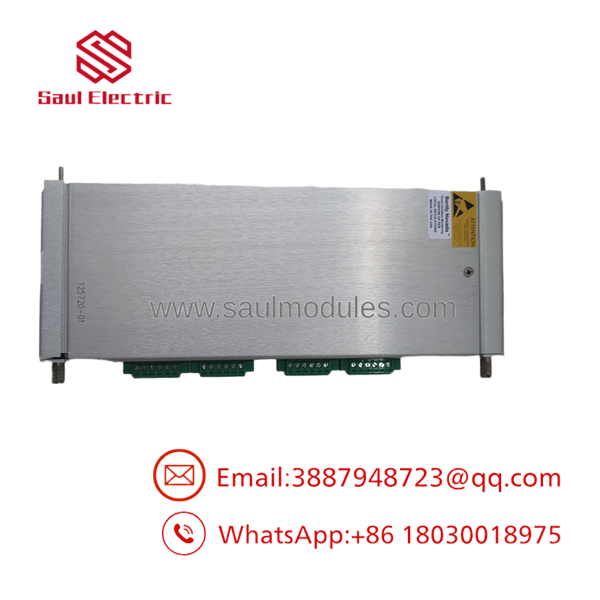
3500/32 125720-01
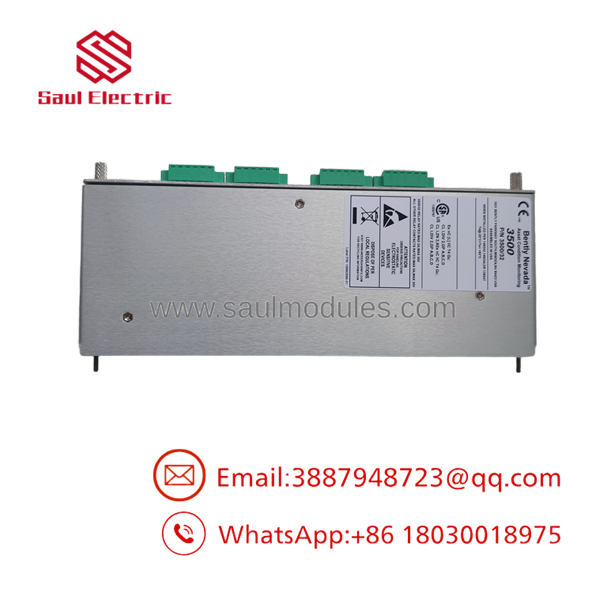
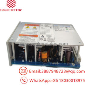
3500/32 125720-01
Transparency SOP: Quality Assurance & Testing
Relay cards drive actual machine trips. We do not just power them up; we test every 125720-01 module under live electrical loads before it ships:
- Physical & Contact Audit: Inspect the multi-layer PCB for trace corrosion, dry solder joints, damaged edge connectors, and visual signs of arcing or pitted contact pins.
- Backplane Insertion & Firmware Verification: Seat the 125720-01 in an active 3500 chassis. Confirm the rack configuration software identifies the card, matches firmware, and clears hardware faults.
- Relay Coil Actuation Test: Force relay state changes (Normally Open to Normally Closed) on all 4 channels via software control. Confirm clear audible contact switching and zero coil drive latency.
- Contact Resistance & Load Verification: Measure dry-contact terminal resistance using a calibrated micro-ohmmeter across both NO and NC terminals to ensure less than 0.1 Ohms path resistance under load.
- Anti-Static Packaging: Vacuum-seal the card in metallic ESD shielding bags with fresh desiccant and pack inside custom foam-lined shipping boxes.
The Veteran’s Tech Trap Guide (Crucial Value-Add)
- ⚠️ 3500/32 (4-Channel) vs. 3500/33 (16-Channel) Confusion: Do NOT mix up the 3500/32 and 3500/33 modules! The 3500/32 125720-01 uses a full-height 4-channel card layout with DPDT contacts. Trying to load a 3500/32 software configuration file onto a 3500/33 16-channel card position will throw a permanent Rack Configuration Error.
- ❗ Normally Energized vs. Normally De-Energized: Check your jumper settings and software configuration carefully! In safety trip applications, relays are typically configured as “Normally Energized” (fail-safe mode, so a loss of power trips the machine). If you configure the software as “Normally De-Energized,” a total rack power loss will not actuate your trip circuit!
- ⚠️ Mating Rear Relay I/O Modules: Ensure the rear I/O module (such as 125712-01 or 125808-01) matches the front 125720-01 card. Always verify terminal block wiring numbers on the back before powering up; landing 120 VAC control lines on the wrong screw terminal will destroy the onboard sensing circuits.
- ❗ Hot-Swapping Precaution: You can hot-swap the 125720-01 front card while the rack is running, but you MUST bypass or isolate the external master trip bus at your DCS/ESD panel first. Pulling the card drops power to the relay coils, which will instantly trigger a machine trip if wired in a fail-safe (normally energized) circuit!
Frequently Asked Questions (FAQ for Conversion)
Q: What is the difference between part number 3500/32 and board number 125720-01?
A: “3500/32” is the complete system designation for the 4-Channel Relay Module assembly. “125720-01” is the specific part number of the main front circuit board itself.
Q: Are the relay outputs on the 3500/32 125720-01 dry contacts?
A: Yes. All 4 channels provide isolated, dry (unpowered) DPDT relay contacts. You must supply external control loop voltage (AC or DC) across the contacts to drive external circuits.
Q: Can I program one relay channel to respond to multiple vibration channels?
A: Yes. The 3500 software allows complex logic combinations (AND/OR logic). You can program a single relay to actuate based on alarms originating from any combination of channels across the entire 3500 rack.
Q: Are these cards new surplus or reconditioned?
A: We hold both New Surplus (factory-sealed, unused OEM stock) and fully bench-tested re-certified units. Every module undergoes complete electrical load and contact testing before dispatch.
Q: What warranty is included with the 125720-01 relay card?
A: We provide a full 12-month replacement warranty on every 3500/32 125720-01 module starting from the delivery date.
Q: Why source 3500/32 modules through surplus channels instead of factory direct?
A: Factory lead times for Bently Nevada relay cards can take several months. We maintain physical, bench-tested inventory ready for immediate shipment, helping you maintain safety compliance and avoid unscheduled downtime.

 Start Chat


