





Description
Engineering Value
When a DCS or PLC must operate an older pneumatic control valve, the E69F-BI2-MS provides the required interface without replacing the valve actuator or installing a separate digital positioner. It accepts a standard analog control signal and produces a pneumatic output suitable for a valve actuator, damper, or pneumatic instrument.
The E69F family supports direct and reverse action, standard and split-range input configurations, and several pneumatic output ranges. The factory data sheet lists 4–20 mA input resistance at 170 Ω and a standard 3–15 psi output range for the common configuration.
Technical Specifications
| Parameter | Specification |
|---|---|
| Conversion type | Current-to-pneumatic, or I/P |
| Standard input | 4–20 mA DC |
| Other supported input ranges | 4–12, 12–20, 10–50, 10–30, or 30–50 mA, depending on factory configuration |
| Input resistance | 170 Ω for 4–20 mA; 27 Ω for 10–50 mA |
| Standard pneumatic output | 3–15 psi, or 20–100 kPa |
| Additional output ranges | 1–18, 1–32, 3–27, and 6–30 psi equivalents, depending on configuration |
| Output action | Direct or reverse |
| Required supply pressure | At least 3 psi or 20 kPa above maximum output signal |
| Nominal supply pressure | 20 psi for 3–15 psi output; 35 psi for higher output ranges |
| Calibrated accuracy | ±0.5% of span for standard output ranges |
| Accuracy for extended ranges | ±2% of span for 1–18 psi and 1–32 psi ranges |
| Air consumption | Approximately 0.30 cfm for the 3–15 psi range with the 40G relay |
| Normal operating temperature | −20 to +140°F, or −30 to +60°C |
| Operative temperature limits | −40 to +180°F, or −40 to +80°C |
| Approximate mass | 5 lb, or 2.3 kg |
| Input power | Loop-powered; no separate electrical supply is normally required |
The supply-pressure requirement matters. A 3–15 psi output should normally receive approximately 20 psi instrument air, while higher output ranges require the corresponding higher supply pressure. Supplying inadequate air pressure can cause output saturation, sluggish response, or poor span calibration.
Field Application
A refinery steam-pressure loop used an older pneumatic valve actuator with a 3–15 psi input. During a DCS cabinet upgrade, the existing analog output was retained, but the original I/P converter began drifting near the low end of the range. A technician installed an E69F replacement and initially saw only 2.5 psi at a 4 mA command. The cause was not the analog card; the instrument-air regulator had been left at 17 psi, below the required supply margin.
After restoring the supply to approximately 20 psi, checking the 4 mA and 20 mA endpoints, and confirming direct action, the valve traveled correctly across its operating range.
Practical application scenarios include:
- Steam pressure control on a turbine extraction valve with a legacy pneumatic actuator.
- Combustion-air damper control on a fired heater using a 3–15 psi pneumatic signal.
- Split-range control of a process valve pair, where one actuator receives 4–12 mA and the other receives 12–20 mA.
- Boiler drum-level control using a pneumatic feedwater valve and a remote DCS analog output.
- Air-operated process dampers in older utility or chemical-processing control systems.
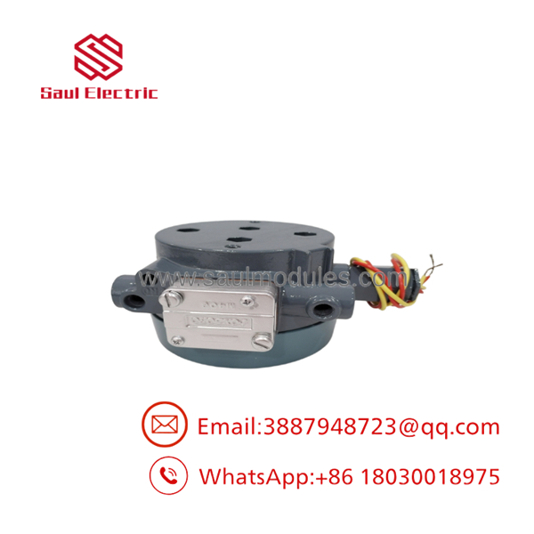
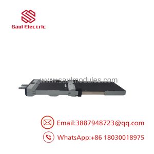
E69F-BI2-MS
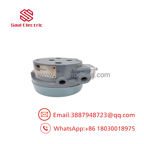
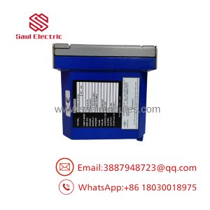
E69F-BI2-MS
QA and Testing SOP
For new-surplus or refurbished E69F-BI2-MS inventory, testing should be performed against the exact nameplate configuration:
- Photograph and record the full model code, serial number, input range, output range, action, and certification marking.
- Inspect the case, cover, conduit entries, terminal connections, relay assembly, tubing, mounting hardware, and gasket surfaces.
- Connect clean, dry instrument air at the pressure specified for the unit’s output range.
- Apply 4, 8, 12, 16, and 20 mA, or the applicable split-range values.
- Record pneumatic output at each test point and verify direct or reverse response.
- Check zero, midpoint, and span performance after the unit has stabilized.
- Verify that the output does not oscillate, stick, or drift after a step change in input.
- Inspect the relay for contamination and confirm that the restrictor and nozzle are not obstructed.
- Document the final calibration results and include a pressure-gauge accuracy statement.
“New surplus” should not automatically be represented as recently calibrated. A stored Foxboro unit may be unused but still require bench testing, especially if it has been exposed to warehouse humidity, contaminated instrument air, or long-term seal aging.
Veteran’s Tech Trap Guide
⚠️ Trap 1: Confusing the converter with a positioner.
The E69F produces pneumatic pressure; it does not necessarily provide valve-position feedback, travel characterization, diagnostics, or actuator calibration functions associated with a modern smart positioner.
⚠️ Trap 2: Installing the wrong action.
An increasing-input/increasing-output unit and an increasing-input/decreasing-output unit are not interchangeable in every loop. Confirm the INC-INC or INC-DEC marking before commissioning.
⚠️ Trap 3: Testing with dirty air.
Oil, water, pipe scale, and thread-sealant fragments can restrict the nozzle or relay. Use clean, dry instrument air and install the correct filtration upstream.
⚠️ Trap 4: Assuming the output range from the front label alone.
The E69F family supports several input and output combinations. Verify the data plate rather than assuming every BI2 unit is 4–20 mA to 3–15 psi.
PRO TIP: During replacement, record the output at 4, 12, and 20 mA before disconnecting the original unit. Those three readings quickly reveal whether the existing loop is direct, reverse, mis-scaled, or mechanically out of calibration.
⚠️ Safety warning: Hazardous-area approval is configuration-specific. The Foxboro instruction manual identifies separate intrinsic-safety, explosionproof, nonincendive, and ATEX options. Use the certification shown on the actual converter and follow the applicable wiring method; never infer approval from the family name alone.
Dynamic FAQ
What does the -BI2-MS do?
It converts a standard electrical current signal into a proportional pneumatic pressure signal. In a common configuration, 4–20 mA becomes 3–15 psi, allowing a DCS or PLC analog output to control a pneumatic actuator or valve.
Does it require a separate power supply?
Normally, no. The 4–20 mA input loop provides the electrical operating signal. The pneumatic side requires a clean instrument-air supply at the correct pressure.
What air pressure should be supplied?
For a 3–15 psi output, the manual specifies a supply at least 3 psi above the maximum output and lists approximately 20 psi as the nominal supply. Higher output ranges require higher supply pressure.
Can the unit be used for split-range control?
Yes, when it is configured with the appropriate split-range input and mechanical spring arrangement. Common split ranges include 4–12 mA and 12–20 mA. Do not assume that a standard unit can be converted in the field without confirming the proper parts and calibration procedure.
How can I verify that a replacement matches my existing unit?
Compare the complete model code and data plate. Confirm input range, pneumatic output range, direct or reverse action, relay type, mounting arrangement, and hazardous-area certification. A visual match alone is not sufficient.
What should a seller provide for new-surplus or refurbished stock?
Request nameplate photographs, serial-number confirmation, enclosure photos, and a test report showing input current versus pneumatic output. The warranty should specify coverage period, return conditions, repair or replacement terms, and whether calibration or functional testing is included.

 Start Chat


