





Description
Engineering Value
This module is intended for 4–20 mA transmitters, self-powered current sources, and other two-wire analog instruments. Each input is galvanically isolated from the other channels and from ground, which helps prevent field-loop ground faults from spreading through the input subsystem.
RH914SQ belongs to the newer Standard and Compact 200 Series documentation set. It can be installed on a modular baseplate, communicate over either path of the redundant 2 Mbps Fieldbus, and be replaced without removing field wiring from the termination assembly.
Technical Specifications
| Parameter | Specification |
|---|---|
| Input signal | 0–20 mA DC |
| Typical transmitter signal | 4–20 mA DC |
| Number of channels | Eight |
| Input wiring | Two-wire DC field input |
| Channel isolation | Each channel isolated from every other channel and earth ground |
| Input impedance | 61.5 Ω nominal |
| Analog accuracy | ±0.03% of span, including linearity |
| Accuracy temperature coefficient | ±50 ppm/°C |
| A/D conversion | Independent sigma-delta converter per channel |
| Integration period | Software configurable |
| Common-mode rejection | Greater than 100 dB at 50/60 Hz |
| Normal-mode rejection | Greater than 95 dB at 50/60 Hz |
| Fieldbus | Redundant 2 Mbps module Fieldbus |
| Power input | 24 VDC, +5%/−10% |
| Power consumption | 7 W |
| Heat dissipation | 3 W maximum |
| Channel protection | Current limited and voltage regulated |
| Maximum input current limit | Normal design limits input below 30 mA; fault-limited current approximately 100 mA |
| Isolation withstand | 600 VAC for one minute between any channel and ground or between channels |
| Operating temperature | −20 to +70°C, or −4 to +158°F |
| Storage temperature | −40 to +70°C, or −40 to +158°F |
| Relative humidity | 5–95%, noncondensing |
| Environmental rating | Suitable for ISA S71.04 Class G3 harsh environments |
| Vibration rating | 0.75 g from 5 to 500 Hz |
| Approximate mass | 284 g, or 10 oz |
| Module dimensions | 102 mm high × 45 mm wide × 104 mm deep; 114 mm high with mounting lugs |
The manufacturer specifies a new analog input reading approximately every 25 ms, with a programmable integration period for averaging and noise reduction. The RH914SQ module is also compatible with standard HART signals, although the actual HART pass-through or communication function depends on the associated transmitter, termination arrangement, and DCS application.
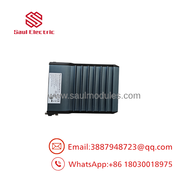
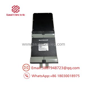
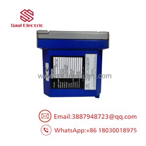
FBM201 RH914SQ
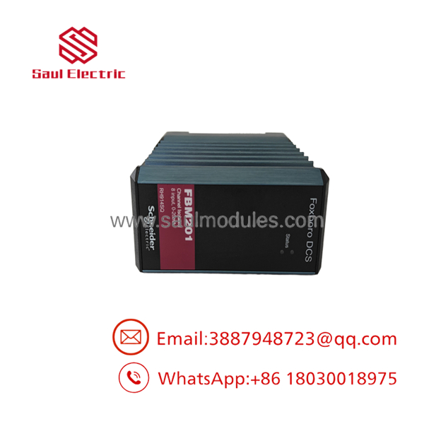
FBM201 RH914SQ
Field Application
A petrochemical unit used eight 4–20 mA pressure and flow transmitters on a Compact 200 I/O subsystem. After a failed FBM201 was replaced, seven channels returned normally, but one flow transmitter showed a slightly unstable value. A loop calibrator at the transmitter terminals produced a stable 14 mA signal, so the instrument itself was not the immediate cause.
The maintenance team traced the issue to a damaged termination cable between the RH916XG termination assembly and the FBM baseplate. Replacing the cable restored the signal without disturbing the field wiring. The event reinforced a useful troubleshooting rule: test the transmitter, termination assembly, cable, module channel, and DCS value as separate points.
Practical applications include:
- Flow transmitter inputs on crude-oil, solvent, and chemical transfer lines.
- Pressure transmitters on reactor, compressor, and steam systems.
- Differential-pressure transmitters for filter, separator, and exchanger monitoring.
- Level transmitters on storage tanks and process vessels.
- Analyzer current outputs for pH, conductivity, oxygen, and gas-monitoring systems.
- Remote 4–20 mA signals routed through a termination assembly in an adjacent cabinet.
QA and Testing SOP
The RH914SQ does not require routine module or termination-assembly calibration according to the published specification, but replacement inventory should still receive a functional test.
- Record the RH914SQ part number, revision, serial number, baseplate position, and termination-assembly part number.
- Inspect the aluminum housing, backplane connectors, Fieldbus connectors, LEDs, and mounting lugs.
- Apply redundant 24 VDC power within the stated tolerance.
- Confirm module startup and communication through both Fieldbus paths.
- Inject 0, 4, 12, 16, and 20 mA into each channel using a calibrated current source.
- Verify DCS values, channel identification, engineering-unit scaling, alarms, and integration settings.
- Confirm channel-to-channel and channel-to-ground isolation.
- Check for excessive input impedance, unexpected loop loading, or current-limit behavior.
- Test the termination cable and confirm the correct RH916XG or P0917JK termination arrangement.
- Record all readings, test equipment, configuration data, and final status.
A valid test record should demonstrate all eight channels. Testing one channel and describing the entire module as “tested” is not enough for a critical process-control spare.
Veteran’s Tech Trap Guide
⚠️ Trap 1: Confusing RH914SQ with voltage-input variants.
RH914SQ is the 0–20 mA module. FBM201b, FBM201c, and FBM201d use different signal ranges and different part numbers. Do not substitute a voltage-input variant for a current-input loop.
⚠️ Trap 2: Using the wrong termination assembly.
For the FBM201 current-input version, the manufacturer lists RH916XG compression and P0917JK ring-lug termination assemblies. A termination assembly for the 0–100 mV, 0–5 V, or 0–10 V variants is not an acceptable substitute.
⚠️ Trap 3: Forgetting HART loading.
The module is electrically compatible with standard HART signals, but HART communication still depends on the transmitter, loop resistance, termination arrangement, and DCS application. A current reading alone does not prove HART communication.
⚠️ Trap 4: Misinterpreting “600 VAC isolation.”
The 600 VAC figure is a one-minute withstand specification. It does not authorize permanent connection to hazardous-voltage circuits. The published safety warning specifically limits normal analog input use to the stated signal range and applicable electrical-safety requirements.
PRO TIP: If a channel reads correctly at the module terminals but incorrectly in the DCS, inspect the termination cable, channel mapping, input application, engineering scaling, integration period, and Fieldbus path before replacing the transmitter.
Dynamic FAQ
What is the difference between and P0914SQ?
Both references are associated with the Foxboro FBM201 0–20 mA analog input function in different product listings and documentation systems. The current Schneider Electric specification identifies as the FBM201 module part number. Confirm the nameplate and the plant’s approved spare-parts database before ordering.
How many input channels does provide?
It provides eight isolated and independent 0–20 mA analog input channels.
Can it accept standard 4–20 mA transmitters?
Yes. A 4–20 mA transmitter operates within the module’s 0–20 mA input range. The DCS engineering range, alarm limits, damping, and integration settings must still be configured correctly.
Does the module support HART?
The manufacturer states that FBM201 is electrically compatible with standard HART signals. Whether HART variables can be accessed depends on the transmitter, loop arrangement, termination hardware, and configured DCS software.
Which termination assemblies are compatible?
The manufacturer lists RH916XG for compression terminals and P0917JK for ring-lug terminals with the FBM201 0–20 mA input. Termination cables can be selected in lengths up to 30 m, or approximately 98 ft.
How should new-surplus or refurbished stock be validated?
Request nameplate photographs, serial-number confirmation, and an eight-channel test report. The report should show 0–20 mA simulation, redundant 2 Mbps Fieldbus communication, channel isolation, termination-cable verification, and DCS value tracking. The warranty should state whether it covers module failure, communication faults, return freight, and compatibility with the specified baseplate and termination assembly.

 Start Chat


