





Description
Engineering Value
The FBM204 is useful when a control loop requires both measurement and output without dedicating separate modules to each direction. Four 4–20 mA transmitters can be monitored while four corresponding control outputs drive valve positioners, speed references, dampers, or current-controlled actuators.
The input channels use independent sigma-delta conversion, while the output channels provide current-limited, voltage-regulated analog signals. The design supports standard 4–20 mA process signals within the module’s 0–20 mA range and is electrically compatible with standard HART signals.
Technical Specifications
| Parameter | Specification |
|---|---|
| Module type | Mixed analog input/output Fieldbus Module |
| Analog inputs | Four 0–20 mA DC channels |
| Analog outputs | Four 0–20 mA DC channels |
| Nominal operating range | 0–20.4 mA DC |
| Typical input signal | 4–20 mA transmitter or self-powered 20 mA source |
| Input impedance | 61.5 Ω nominal |
| Input accuracy | ±0.03% of span, including linearity |
| Accuracy temperature coefficient | ±50 ppm/°C |
| Input conversion | Independent sigma-delta A/D converter per channel |
| Input integration period | Software configurable |
| Common-mode rejection | Greater than 100 dB at 50/60 Hz |
| Normal-mode rejection | Greater than 95 dB at 50/60 Hz |
| Output resolution | Up to 13 bits, depending on module generation and configuration |
| Maximum output load | Approximately 750 Ω |
| Output accuracy | Approximately ±0.03% of span |
| Input channel protection | Galvanically isolated, current limited, and voltage regulated |
| Input current limit | Normal design limit below 30 mA; fault-limited current approximately 100 mA |
| Output response | Approximately 30 ms or less, depending on configuration |
| Fieldbus | Redundant 2 Mbps module Fieldbus |
| Module power | 24 VDC, +5%/−10% redundant input |
| Power consumption | Approximately 7 W maximum |
| Heat dissipation | Approximately 3 W |
| Operating temperature | Typically −20 to +70°C, or −4 to +158°F, for the current Compact specification |
| Storage temperature | Approximately −40 to +70°C |
| Relative humidity | 5–95%, noncondensing |
| Environmental classification | ISA S71.04 Class G3 harsh environment |
| Isolation withstand | Approximately 600 VAC for one minute between channel-to-ground and channel-to-channel circuits |
The official FBM204 documentation confirms four 0–20 mA input channels and four 0–20 mA output channels, with independent channel isolation, 61.5 Ω nominal input impedance, ±0.03% span accuracy, and a 24 VDC redundant input supply.
Field Application
A water-injection skid used four flow and pressure transmitters on the FBM204 inputs and four current outputs to control metering-pump speed references and injection valves. After a replacement module was installed, the input values were correct, but one pump remained at minimum command even when the DCS output was increased.
The technician measured the FBM204 output at the terminal block and found that the current rose correctly from 4 to 20 mA. The problem was downstream: the pump controller’s input common had been landed on the wrong terminal after a termination-assembly change. The module was functioning correctly; the field wiring was not.
Practical applications include:
- Four pressure inputs and four valve-position commands on a chemical dosing skid.
- Boiler feedwater pressure and flow inputs with four modulating valve outputs.
- Compressor suction/discharge monitoring with speed-reference outputs.
- Cooling-tower flow and temperature transmitter inputs with fan-speed outputs.
- Reactor pressure, level, and flow loops where multiple outputs share a compact DCS baseplate.
- Pump-station control using transmitters on the input side and VFD or positioner references on the output side.
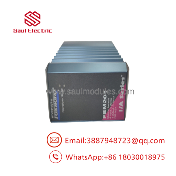
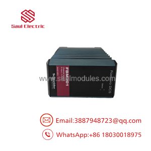
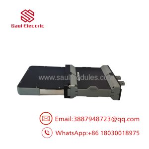
FBM204
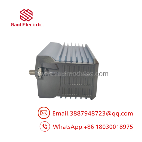
FBM204
QA and Testing SOP
The FBM204 should be tested as two separate functional groups: four input channels and four output channels.
- Record the full module number, suffix, revision, serial number, termination assembly, and baseplate position.
- Inspect the module housing, connectors, mounting hardware, LEDs, and Fieldbus interface.
- Apply redundant 24 VDC power within the manufacturer’s tolerance.
- Confirm module startup and communication through both Fieldbus paths.
- Inject 0, 4, 12, 16, and 20 mA into each of the four input channels.
- Verify the reported DCS value, scaling, alarm status, and input filtering.
- Command 0, 4, 12, 16, and 20 mA on each output channel.
- Measure output current with a calibrated load and confirm output stability.
- Test output performance at a representative load, including the expected positioner or controller input impedance.
- Check channel-to-channel and channel-to-ground isolation.
- Verify that input and output terminals are landed on the correct sides of the termination assembly.
- Record current readings, DCS values, output-load conditions, Fieldbus status, and test equipment identification.
A seller should not describe the unit as fully tested after checking only the input side. A mixed I/O module can have functioning inputs and failed outputs, or the reverse.
Veteran’s Tech Trap Guide
⚠️ Trap 1: Treating all FBM204 versions as identical.
Legacy, Compact, and current EcoStruxure Foxboro versions can use different termination assemblies, dimensions, mounting structures, and order-code conventions. Confirm the full part number, not just .
⚠️ Trap 2: Confusing inputs and outputs at the termination assembly.
The module has four channels in each direction. A wiring error can place a transmitter on an output terminal or connect an actuator to an input terminal.
⚠️ Trap 3: Ignoring output load.
The output must have enough compliance voltage for the connected positioner, isolator, cable, and input resistor. A current output that reaches 20 mA on an unloaded bench may fail under the real field load.
⚠️ Trap 4: Assuming a valid input guarantees a valid control output.
The input loop, DCS logic, output channel, field wiring, actuator input, and final element must be checked separately.
PRO TIP: Test each output with a calibrated 250 Ω or 500 Ω load before connecting the field device. Then repeat the test with the actual positioner or controller connected.
⚠️ HART note: Electrical compatibility with HART signals does not guarantee that HART variables or diagnostics will be available in the DCS. That depends on the transmitter, loop design, termination hardware, and application software.
Dynamic FAQ
What does the provide?
It provides four analog input channels and four analog output channels. Both directions use 0–20 mA DC signals, making the module suitable for mixed monitoring and control applications.
Can the accept standard 4–20 mA transmitters?
Yes. A standard 4–20 mA transmitter operates within the module’s 0–20 mA input range. The DCS must still have the correct engineering-unit scaling and alarm configuration.
What can the analog outputs drive?
The outputs can drive compatible current-input devices such as valve positioners, pneumatic I/P converters, motor-speed controllers, dampers, and signal isolators. Confirm the receiving device’s input impedance and minimum voltage requirement.
Is each channel isolated?
The manufacturer specifies channel-to-channel isolation and isolation from ground for the analog channels. The module also includes current limiting and voltage regulation on the input circuits.
Which part numbers are associated with ?
Common order-code references include P0914SY and RH914SY, but the correct replacement depends on the I/A Series or EcoStruxure Foxboro hardware generation, termination assembly, and installation type. Verify the nameplate and system documentation before ordering.
How should new-surplus or refurbished stock be validated?
Request the full nameplate, serial number, revision, and termination-assembly details. Testing should include all four inputs, all four outputs, representative output loads, redundant Fieldbus communication, channel isolation, and DCS value verification. The warranty should state whether it covers both input and output channels, communication faults, return freight, and compatibility with the buyer’s Foxboro baseplate.

 Start Chat


