





Description
Engineering Value
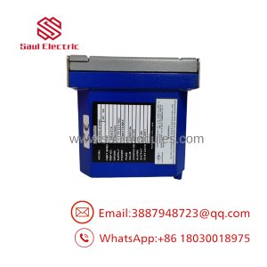
FBM02 modules are used where temperature inputs must be isolated at the field interface before conversion and transmission through the DCS Fieldbus. Each channel can accept standard thermocouple types or other millivolt signals, while the reference-junction circuit supports thermocouple cold-junction compensation.
For plant maintenance teams, the key value is channel density without sacrificing channel-to-channel isolation. The module also supports configurable integration periods, allowing the control engineer to trade response time against resolution and noise performance.
Technical Specifications
| Parameter | Specification |
|---|---|
| Input type | Isolated thermocouple and millivolt input |
| Number of input channels | Eight |
| Channel isolation | Inputs are isolated and independent |
| Input range | −10.5 to +71.41875 mV DC |
| Reference-junction channel | One isolated channel |
| Reference-junction sensor | 100 Ω platinum RTD |
| Supported RTD connection | Two-wire, three-wire, or four-wire RTD when using a plug termination |
| Common thermocouple types | B, E, J, K, S, T, and N |
| Millivolt accuracy | ±0.035% of span, or ±0.028 mV |
| RTD channel accuracy | ±0.025% of span, or approximately ±0.2°C |
| Thermocouple conformity | ±0.25°C |
| RTD conformity | ±0.25°C |
| Reference-junction measurement accuracy | ±0.50°C when using the supplied RTD arrangement |
| Input open-circuit voltage | 0.25 V DC on mV channels |
| Resolution options | 12, 13, 14, or 15 bits, based on selected integration period |
| Integration periods | 0.1, 0.2, 0.5, or 1.0 second |
| Update time | Approximately 10–50 ms, depending on integration setting |
| Communication | Redundant Fieldbus |
| Supply voltage | 26–42 VDC redundant input |
| Maximum consumption | 9 W |
| Operating temperature | 0–60°C, or 32–140°F |
| Storage temperature | −40–70°C, or −40–158°F |
| Relative humidity | 5–95%, noncondensing |
| Mass | Approximately 1 kg, or 2.2 lb |
At the shortest 0.1-second integration period, the module provides 12-bit resolution with approximately 10 ms update time. At a 1.0-second integration period, resolution increases to 15 bits and the update time is approximately 50 ms. The specified settling time also increases as filtering and resolution are increased.
Field Application
A fired-heater control loop began showing erratic stack-temperature values after a maintenance team replaced a failed FBM02. The new module passed a basic power-up check, but two channels read several degrees low. The wiring was correct. The problem was a mismatch between the configured thermocouple type and the installed sensors: the original loop used Type K thermocouples, while the replacement configuration had been restored with a Type J selection.
After correcting the channel configuration and checking the common reference-junction RTD, all eight temperature values returned to expected readings. The plant avoided replacing four field sensors that had initially been blamed for the error.
Niche applications include:
- Furnace bridgewall and tube-skin temperature monitoring in a refinery heater.
- Economizer outlet and superheater metal-temperature measurement in a utility boiler.
- Reactor jacket-temperature monitoring where multiple isolated Type K inputs share one field enclosure.
- Heat-treatment furnace zone monitoring using thermocouples and direct millivolt transmitters.
- Compressor discharge-temperature monitoring with long field cable runs and high electrical noise.
The FBM02 is especially useful when the field wiring includes mixed thermocouple types or low-level mV signals, but every channel must be configured and terminated for the intended sensor circuit.
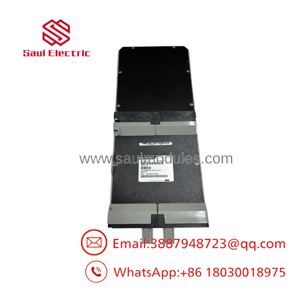
FBM02
QA and Testing SOP
For new-surplus or refurbished FBM02 stock, testing should be performed with the correct termination assembly and a calibrated thermocouple/mV simulator:
- Record the complete part number, revision, serial number, and termination-assembly type.
- Inspect the module housing, backplane connector, Fieldbus connector, status LEDs, and retaining hardware.
- Confirm the module is installed in an approved Foxboro I/A Series mounting structure.
- Apply redundant DC power within the specified 26–42 VDC range.
- Verify module startup, operational status indication, and Fieldbus communication.
- Inject known millivolt values into all eight channels.
- Check each channel for correct scaling, isolation, linearity, and open-circuit behavior.
- Test the reference-junction input with a calibrated 100 Ω platinum RTD simulator.
- Exercise representative Type B, E, J, K, N, S, and T configurations where the test equipment supports them.
- Record results at low, midpoint, and high input values, including the selected integration period.
A seller should not describe an FBM02 as tested merely because its LEDs illuminate. A meaningful test should demonstrate input conversion, Fieldbus communication, reference-junction operation, and channel isolation.
Veteran’s Tech Trap Guide
⚠️ Trap 1: Confusing FBM02 with FBM202.
The part numbers are similar, but the hardware, termination arrangements, power requirements, and system-generation details can differ. Verify the actual installed module and I/A Series revision before making a substitution.
⚠️ Trap 2: Ignoring the reference-junction circuit.
A thermocouple channel can appear electrically healthy while producing inaccurate temperature values if the cold-junction RTD is missing, miswired, or configured for the wrong termination method.
⚠️ Trap 3: Mixing thermocouple materials.
Do not extend a Type K circuit with ordinary copper wire or install the wrong compensating cable. The signal may look plausible at room temperature and then drift badly as the termination temperature changes.
⚠️ Trap 4: Treating 0.25 V open-circuit voltage as a sensor supply.
The mV input’s open-circuit voltage is a measurement characteristic, not a field excitation source for a conventional transmitter.
PRO TIP: Before removing the old module, save the channel configuration, thermocouple types, linearization settings, burnout direction, integration period, and Fieldbus assignment. A hardware replacement without the original configuration can create a control-room problem even when the new module is electrically good.
⚠️ Maintenance warning: Use proper ESD controls. The module interfaces directly with low-level analog circuitry and a DCS communication bus; handling it by the terminal pins or Fieldbus connector can introduce intermittent faults that are difficult to reproduce.
Dynamic FAQ
What signals can the accept?
It accepts eight isolated thermocouple or millivolt input signals. The full mV input range is −10.5 to +71.41875 mV DC. Typical thermocouple types include B, E, J, K, S, T, and N.
Does the include cold-junction compensation?
Yes. It has one isolated reference-junction compensation channel. Direct and wire-type termination assemblies use a 100 Ω platinum RTD arrangement, while plug termination can use a user-supplied two-, three-, or four-wire 100 Ω platinum RTD.
Is the a standalone PLC module?
No. It is an I/A Series DCS Fieldbus module. It communicates through the redundant Fieldbus and is installed in Foxboro mounting and termination hardware.
What is the difference between and FBM202?
Both are associated with thermocouple/mV input functions, but they are not automatically interchangeable. The module generation, termination assembly, Fieldbus architecture, firmware, power requirements, and system compatibility must be checked against the existing I/A Series installation.
What should be checked before ordering a replacement?
Confirm the full hardware part number, module revision, termination assembly, mounting structure, Fieldbus arrangement, channel configuration, and required thermocouple types. Also verify whether the plant requires a main module, redundant module, or a specific system-approved revision.
How should new-surplus or refurbished stock be validated?
Request clear photos of the module label and connectors, serial-number confirmation, and a test record. The report should include redundant power-up, status LEDs, Fieldbus communication, all eight input channels, reference-junction operation, and representative mV or thermocouple simulation. A warranty should state whether it covers replacement, repair, return freight, and compatibility with the buyer’s specified I/A Series hardware.

 Start Chat


