





Description
Engineering Value
The FBM202 lets an I/A Series or EcoStruxure Foxboro DCS acquire direct thermocouple signals without adding individual temperature transmitters for every measurement point. Its isolated channels reduce the effect of ground-potential differences and field wiring faults on adjacent temperature inputs.
Cold-junction compensation is built into the module arrangement through the isolated RTD reference input. That is valuable in furnaces, boilers, reactors, and heat exchangers where direct thermocouple wiring is preferred for response time or maintenance reasons.
Technical Specifications
| Parameter | Specification |
|---|---|
| Input type | Thermocouple and millivolt |
| Number of channels | Eight isolated and independent thermocouple/mV inputs |
| Reference-junction input | One isolated RTD channel |
| Input range | −10.5 to +69.5 mV DC |
| Full-scale raw-count point | 71.419 mV DC corresponds to 65,535 counts |
| Differential input impedance | 10 MΩ |
| Common-mode voltage | Up to 30 VAC or 60 VDC |
| Supported sensor types | Common types include B, E, J, K, N, R, S, and T; confirm the configured module revision for the complete list |
| Thermocouple conformity | Approximately ±0.25°C |
| RTD reference-junction conformity | Approximately ±0.25°C |
| RTD measurement accuracy | Approximately ±0.50°C when using the specified Foxboro termination assembly |
| Input open-circuit voltage | Approximately 250 mV DC through 10 MΩ on mV channels |
| Input filtering | Configurable integration period |
| Conversion | Digital analog-to-digital conversion per channel |
| Communication | Redundant 2 Mbps module Fieldbus |
| Power input | 24 VDC, +5%/−10% |
| Module power | Approximately 3 W for the legacy module specification; verify the exact Compact variant |
| Isolation withstand | Approximately 600 VAC for one minute between channel-to-ground and channel-to-channel circuits |
| Operating temperature | Approximately −20 to +70°C, or −4 to +158°F, for the Compact specification |
| Storage temperature | Approximately −40 to +70°C, or −40 to +158°F |
| Relative humidity | 5–95%, noncondensing |
| Environmental class | ISA S71.04 Class G3 harsh environment |
| Approximate dimensions | 102 mm high × 45 mm wide × 104 mm deep; approximately 114 mm high with mounting lugs |
| Approximate mass | 284 g, or 10 oz |
The FBM202 family includes multiple hardware generations and order-code variants. The legacy FBM202 specification lists P0916FH as a common module reference, while the Compact documentation uses newer part-number families such as P0926EQ. Do not use the generic FBM202 designation alone to determine power consumption, termination hardware, or replacement compatibility.
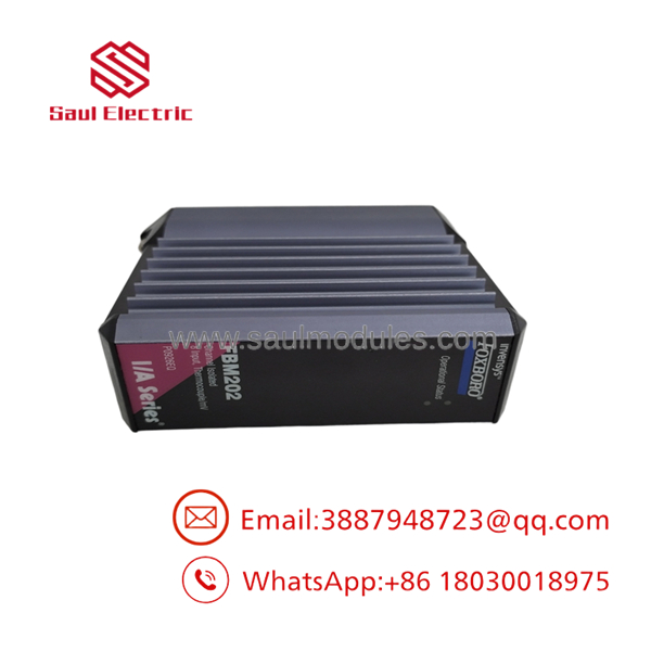
FBM202
Field Application
A power plant used FBM202 channels for boiler superheater outlet temperatures, furnace-wall temperatures, and steam-drum measurements. After a module replacement, one Type K channel read several degrees high while the remaining channels were stable. A resistance check on the thermocouple loop showed no open circuit, and a field calibrator produced the expected millivolt signal.
The fault was traced to the reference-junction circuit. The replacement termination assembly was not the one specified for the installed FBM202 revision, so the terminal-temperature compensation value was incorrect. After installing the correct termination assembly and verifying the reference RTD, the Type K reading agreed with the calibrated test source.
Typical applications include:
- Boiler superheater and reheater outlet-temperature monitoring.
- Refinery furnace tube-skin and bridgewall-temperature measurement.
- Reactor-bed temperature profiling in chemical processing.
- Heat-treatment furnace zone monitoring.
- Turbine exhaust and bearing-housing temperature acquisition.
- High-temperature process skid monitoring where direct thermocouple wiring is retained.
QA and Testing SOP
Because the name covers more than one hardware generation, the test plan must begin with part-number identification:
- Record the complete module part number, revision, serial number, and termination assembly.
- Confirm whether the module is a legacy I/A Series unit or a Compact EcoStruxure Foxboro version.
- Inspect the housing, backplane connectors, Fieldbus connectors, status LEDs, and mounting hardware.
- Apply 24 VDC within the specified tolerance.
- Verify startup diagnostics and communication through both redundant Fieldbus paths.
- Simulate representative thermocouple signals with a calibrated thermocouple or millivolt source.
- Test all eight input channels at low, midpoint, and high values.
- Verify the 100 Ω platinum RTD reference-junction input.
- Confirm correct thermocouple type, burnout direction, units, filtering, and channel scaling.
- Check for channel-to-channel interaction and unexpected ground leakage.
- Record simulated input, reported temperature, reference-junction value, alarm state, and Fieldbus status.
A module should not be labeled “tested” solely because it powers up. The test record should demonstrate temperature conversion, reference-junction compensation, channel isolation, and communication with the intended Foxboro system.
Veteran’s Tech Trap Guide
⚠️ Trap 1: Confusing with FBM201.
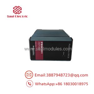
FBM201 is associated with analog current or voltage inputs. is for thermocouple and millivolt signals. Installing the wrong family can create an apparently active module with unusable field values.
⚠️ Trap 2: Ignoring hardware generation.
Legacy and Compact modules may use different termination assemblies, cables, power specifications, and system hardware. Match the full part number, not just “.”
⚠️ Trap 3: Forgetting cold-junction compensation.
A correct thermocouple millivolt signal can still produce an incorrect temperature when the reference-junction RTD or termination assembly is wrong.
⚠️ Trap 4: Applying the wrong thermocouple linearization.
A Type J channel configured as Type K may produce a plausible value at one temperature and a substantial error across the operating range.
PRO TIP: Capture the original thermocouple type, burnout setting, input filter, reference-junction configuration, engineering units, and Fieldbus assignment before removing the module.
⚠️ Safety warning: Thermocouple circuits connected to high-energy equipment can carry hazardous common-mode voltage. Respect the specified 30 VAC or 60 VDC common-mode limit and the site’s isolation and grounding requirements.
Dynamic FAQ
What type of signals does accept?
It accepts thermocouple and millivolt input signals. The current Compact specification lists an input range of −10.5 to +69.5 mV DC, while specific thermocouple types are selected through the module and DCS configuration.
How many inputs are provided?
The module provides eight isolated thermocouple/mV input channels plus one isolated RTD reference-junction compensation channel.
Does support cold-junction compensation?
Yes. The module uses an isolated RTD reference-junction input for terminal-temperature compensation. The correct RTD, termination assembly, and DCS configuration must be used.
What is the difference between P0916FH and P0926EQ?
They belong to different documentation and hardware-generation contexts. P0916FH is associated with the legacy I/A Series specification, while P0926EQ appears in Compact Foxboro documentation. Confirm baseplate, Fieldbus, termination, firmware, and environmental requirements before substituting one for the other.
Can accept a 4–20 mA transmitter?
No. is not a general-purpose current-input module. A 4–20 mA transmitter normally requires an appropriate FBM201 or another approved analog-input module.
How should new-surplus or refurbished stock be validated?
Request the complete nameplate, serial number, revision, termination-assembly details, and proof of system compatibility. Testing should include all eight channels, representative thermocouple or mV simulation, reference-junction verification, redundant Fieldbus communication, and channel-isolation checks. The warranty should specify repair or replacement coverage, return terms, and compatibility with the buyer’s exact Foxboro hardware generation.

 Start Chat


